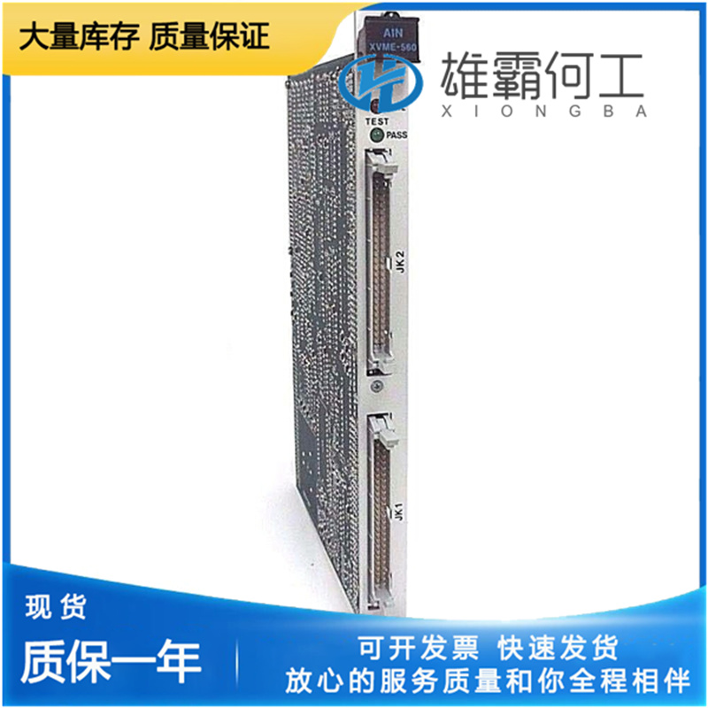
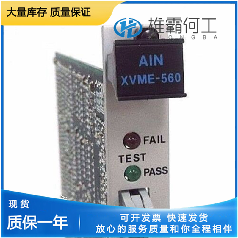
LAM 605-707109-001 控制板
产品概述:
605-707109-001200最小值(mA)dflt=20 mA(范围0.0–200)模拟输入最小需求值,单位为mA。此设置对应于要求致动器完全关闭(0%)的毫安信号(应小于“605-707109-001”设置)。AnlgIn 200最大值(mA)dflt=180 mA(范围0.0–200)模拟输入最大需求值,单位为mA。此设置对应于要求致动器完全打开(100%)的毫安信号(应大于“AnlgIn 200Min Value(mA)”设置)。CAN数据速率默认值=1(1,3)CAN数据速率设置,单位为kbps。选择选项:1=250、2=500、3=1000 kbps。CAN扩展默认值=1(0,1)CAN扩展配置。这决定了605-707109-001通信的消息。605-707109-001使用J1939 CAN,但此设置设置了要通过通信链路使用的实际参数组号(PGN)和可疑参数号(SPN)。选择选项:0=禁用Can通信,1=设置#1,2=设置#2等(如果配置了Can需求,则必须大于零)。PwmIn最小占空比(%)默认值=10%(范围10–90)PWM最小执行器位置占空比设置,单位为百分比。该设置对应于要求致动器完全关闭的占空比(0%)(必须小于“PwmIn Max duty(%)”设置)。605-707109-001最大占空比(%)默认为90%(范围10–90)PWM最大执行器位置占空比设置,单位为百分比。该设置对应于要求执行机构全开(100%)的占空比(必须大于“PwmIn Min duty(%)”设置)。

温度保护启用dflt=true(false,true)温度保护配置。这实现了基于温度的电流限制,并且是温度保护和补偿的结合。当设置为true(推荐)时,当内部执行器温度超过绝对故障水平时,提供保护以限制驱动电流输出。605-707109-001当设置为false时,将绕过此保护。当绝对故障保护温度限制激活时,会记录报警。同样的算法不仅在非常高的温度下限制电流,而且在非常低的温度下也允许额外的电流(参见第5章中基于温度的电流限制描述)。605-707109-001配置:需求设置需求设置设置ProAct控件的主要和备份需求。参见图9-3。调整模式中提供了其他需求参数。605-707109-001
需求——主要来源dflt=3(1,3)选择主要需求输入的来源。选择选项:1=CAN,2=PWM,3=模拟。Demand--备份源dflt=2(0,3)选择备份请求输入的源。选择选项:0=未使用,1=CAN,2=PWM,3=模拟605-707109-001(主和备用需求源必须不同)。AnlgIn 20最小值(mA)dflt=4 mA(范围0.0–25)模拟输入最小需求值,单位为mA。此设置对应于要求执行机构完全关闭(0%)的毫安信号(应小于“605-707109-001 20最大值(mA”设置)。AnlgIn 20最大值(mA)dflt=20 mA(范围0.0–25)模拟输入最大需求值,单位为mA。此设置对应于要求执行机构完全打开(100%)的毫安信号(应大于“AnlgIn 20最小值(毫安)”设置)。

Enabled (status indication only) Configure Mode Enabled Indication (true/false). Parameter is true when the mode is enabled – this indicates Configure mode parameters can be changed. When false, parameters can only be viewed – not adjusted. Exit dflt = false (momentary true command only) Exit command. Set to true to exit the Configure mode. 605-707109-001This disables the ability to make changes to parameters in this mode. The ‘Exit’ parameter automatically returns to false when the exit is completed. Error Code (status indication only) Integer Indication of the status of the configuration (see also Error Info). An error in the configuration will not allow the actuator to operate and will result in a Configuration Error Shutdown. Error Code Interpretation (same as Error Info below) 0 No errors in configuration 101 Primary / Backup signal selection same 102 Invalid primary demand signal selection 103 Invalid backup demand signal selection 104 Actuator Inertia setting value too large 105 Invalid Actuator type selection 106 Invalid PwmIn max/min duty values 107 Invalid AnalogIn max/min values 108 CAN Extensions must be non-zero Error Info (status indication only) String Indication of the status of the configuration (see also Error Code). An error in the configuration will not allow the actuator to operate and will result in a Configuration Error Shutdown (see information on shutdowns). 605-707109-001Shutdown Command dflt = false (false, true) RS-232 Command to shut the actuator driver down. Refer to shutdowns. Configure: Unit Setup The Unit Setup category sets critical actuator and controller information.605-707109-001 Refer to Figure 9-2. Additional actuator parameters are available in the Service Mode (see ‘Hardware Adjustments’).
106 Invalid PwmIn max/min duty values 605-707109-001(the PWM demand input setting for min duty cycle must be less than the max value) 107 Invalid AnalogIn max/min values (the analog input demand input setting for min must be less than the max value) 108 CAN Extensions must be non-zero (the CAN Extensions setting cannot be zero when CAN is configured as a demand signal. An Extension setting of zero disables the CAN transmissions.) Configure Mode Parameters Overview The Configure Mode is used to set up the parameters for the specific application of the ProAct control. For example, the direction of shaft rotation,605-707109-001 type of actuator, and primary/backup demand selections are set in the Configure mode. This mode can be accessed at any time but parameters can only be changed when the unit is shut down and the password is entered (see Password and Enabled parameters in the Mode category).
Password dflt =0 Password input command for the Configure mode. To enter a value, highlight or delete the default value (‘0’) and use the keypad to enter the numeric password. 605-707109-001The input is accepted when the enter key is pressed or the equals sign to the right of the input is selected. When entered, the password returns to zero. If accepted and the unit is shut down, the ‘Enabled’ indication will be true. Refer to the Appendix for Service Tool passwords.

Exiting Configure Mode Select the Configure Mode tab sheet and set the EXIT value to ‘true’. Return the unit to a running (operational) state by setting the Shutdown Command value back to ‘false’ or by closing the Low Power Standby Mode discrete input. The Service Mode / Unit Status will display ‘running’ if successful (refer to the Service Mode Details section). If an error was made in the unit’s configuration, a Config Error shutdown will hold the driver in a shutdown state.605-707109-001 The exact cause of the Configuration Error is identified on the Configure Mode tab sheet (see Configuration Error section). Configuration Error Upon completion of the configuration, a validity check is performed. If an error is detected, the Config Error shutdown is issued and the unit will not run until it is cleared. The cause of the Configuration Error can be determined from the Error Code and Error Info values on the Configure Mode tab sheet. Error Code Error Info (displayed text) 0 No errors in configuration 101 Primary / Backup signal selection same (the primary demand and backup demands are configured for the same source) 102 Invalid primary demand signal selection (the primary demand selection is configured for an out of range value) 103 Invalid backup demand signal selection605-707109-001 (the backup demand selection is configured for an out of range value) 104 Actuator Inertia setting value too large (the actuator inertia setting selection is configured for an out of range value) 105 Invalid Actuator type selection (the actuator type is configured for an out of range value)

