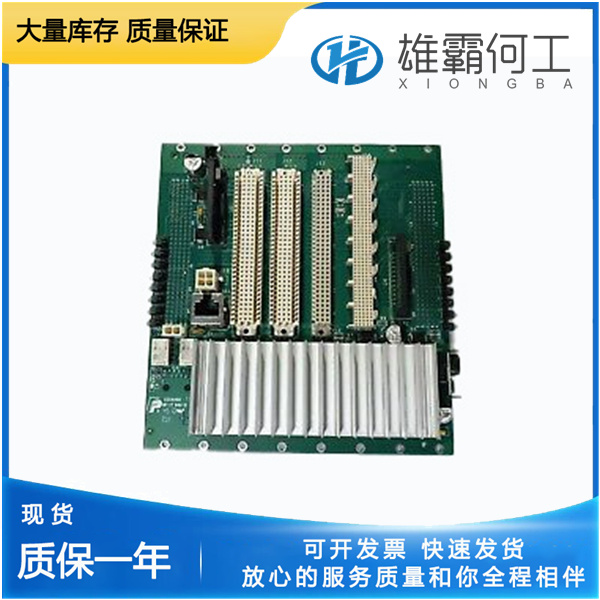
LAM 660-072825-625 射频发生电源
产品概述:
810-015932-001200 Fail Max(mA)dflt=250 mA(100至250)对于200 mA模拟输入范围,模拟输入将被确定为失败的值。如果输入在“Analog In Fail Delay”(模拟输入失败延迟)时间内高于“Fail Max”毫安级,则确定为失败。模拟输入故障延迟(秒)默认值=0.1秒(0.01到10)模拟输入故障延时(秒)。810-015932-001模拟输入滤波器默认值=模拟输入上的0.01(0.0到1.0)滞后τ滤波器调整。模拟输出偏移(mA)默认值=0 mA(-2至24)模拟输出电流上的偏移调整,单位为毫安。AnalogOut增益默认值=1(-1.0到1.5)模拟输出电流的增益调整。增益基于实际位置,在0%时,增益调整没有效果。输出单位为毫安=(实际位置单位为%+4mA)(增益)+偏移。注:如果需要,可以通过将增益设置为-1并将偏移设置为24来反转模拟输出(20-4 mA)。CanIn Fail Min(msg/s)default=30(10到100)CAN请求输入的故障调整。此设置是ProAct在发出故障之前每秒接收的最小消息数。当消息在“Fail Delay”(故障延迟)持续时间内降至“Fail Min”(故障最小值)以下时,表示CAN故障。故障可能是can过慢或can无信号,810-015932-001具体取决于接收到的信息数量。CAN输入故障延迟(秒)默认值=0.3秒(0.1到10)CAN请求信号故障延迟(以秒为单位)。该瞬态电流极限和稳态电流都在最小或最大停止电流极限激活之前主动尝试定位输出——也就是说,在该极限接合之前,电流可能达到瞬态极限,然后是稳态极限。这些设置仅在电流控制器上提供积分限制,因此实际电流可能超过此设置。高于此设置的当前误差与位置误差需求成比例。一旦达到最大(或最小)极限,如果需求继续增加(或减少),810-015932-001电流也将按比例增加。瞬态和稳态电流限制仍然有效——电流不会超过这些限制。需求跟踪误差(%)默认值=15%(1.0到100)当使用冗余需求输入(主和备份)时,需求输入的跟踪误差调整。此设置是在发出跟踪警报之前,控制需求和备用需求之间的最大差值(百分比)。差值必须超过“错误延迟”持续时间的“错误”百分比值才能生成警报。810-015932-001值为“100”将禁用报警。请求跟踪错误延迟(秒)默认值=1秒(0.1到10)跟踪错误延迟,以秒为单位--请参阅请求跟踪错误。

810-015932-001(自动状态)——自动用户停止程序的字符串指示1=失败0=禁用1=启用2=寻找最小停止3=寻找最大停止4=停止设置自动状态Int——自动状态字符串的整数指示(见上文)。手动启用dflt=false命令启用手动用户校准。当为true时,手动设定位置(%)将主动控制驾驶员输出至指令位置。810-015932-001此模式也可用于笔划输出。手动设置位置(%)默认为50%(-10到110)手动位置需求。当启用手动模式时,此需求设置处于活动状态。810-015932-001可用于设置止动器和冲程执行器输出。810-015932-001手动状态——手动用户停止程序的字符串指示1=失败0=禁用1=启用2=最小停止集3=最大停止集手动状态Int——手动状态字符串的整数指示

Actuator Inertia Setting dflt =0 (range 0–25) Actuator/valve inertia setting.810-015932-001 This setting is available for systems with higher or lower inertia than the default as indicated by excessive shaft movement. A zero (0) setting is basically for an unconnected shaft, whereas, increasing the setting implies a higher inertia in the system. Refer to Table 9-1 for an approximate Inertia Setting value based on lever size. High Friction System dflt =false (false, true) Internal Disturbance Observer Controller (dobs) Enable command. Normally set to false, only needed in high friction systems.810-015932-001 As a general rule-of-thumb, when more than 2 A of current are required to move the actuator then a true setting will help with controllability.

To change this parameter, the User Stop mode must be enabled. Actuator Inertia Test Execute Once changed, it is recommended the setting be tested. A quick stability check can be done by selecting the ‘Actr Inertia Test Execute’ command.810-015932-001 This provides a short actuator positioning sequence and can be used to verify the Inertia Setting. The sequence goes to 30 % travel for 3 seconds, then goes to 70 % for 3 seconds and back to 30 % for 3 seconds, concluding the test.810-015932-001 If instability is detected, the test can be aborted by setting the Execute command back to false. In general, if the Inertia Setting is too high the output will have a high frequency oscillation and too low the frequency of oscillation will be much slower or response will be sluggish.

Auto810-015932-001 Status—String indication of the automatic user stop procedure. –1= Failed 0 = Disabled 1 = Enabled 2 = Looking for Min Stop 3 = Looking for Max Stop 4 = Stops Set Auto Status Int—Integer indication of the Auto Status string (see above). Manual Enable dflt = false Command to enable the manual user calibration. When true, the Manual Set Position (%) is actively controlling the driver output to the commanded position. This mode can also be used to stroke the output.810-015932-001 Manual Set Position (%) default 50 % (–10 to 110) Manual position demand. This demand setting is active when the Manual Mode is enabled. Can be used to both set the stops and to stroke the actuator output. Manual Status—String indication of the manual user stop procedure. 810-015932-001–1= Failed 0 = Disabled 1 = Enabled 2 = Min Stop Set 3 = Max Stop Set Manual Status Int—Integer indication of the Manual Status string (see above). Manual—At Min Posn dflt = false (momentary true command only) Command to indicate minimum position is reached. This sets the 0 % (min) position for all position demand signals.810-015932-001 Manual—At Max Posn dflt = false (momentary true command only) Command to indicate maximum position is reached. This sets the 100 % (max) position for all position demand signals. Adjusting and Testing Actuator Dynamics Actuator dynamics are set in the Configure Mode, but can also be adjusted in the Adjust User Stop mode. There is only one adjustable dynamics parameter, it is the Actuator Inertia Setting (see Table 9-1).


