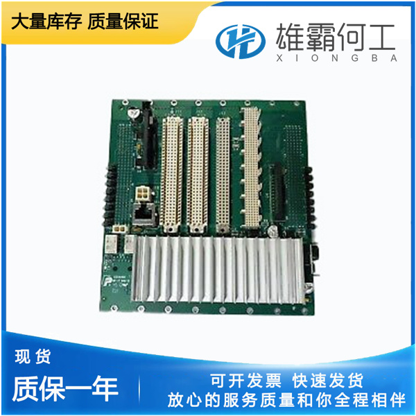
LAM 810-017015-001 电源组件
产品概述:
810-017015-001滤波器默认值=810-017015-001输入上的0.01(0到1)滞后τ滤波器调整。停止——最小停止偏移(度)默认值=0.5度(-10到10)旋转角度的电气停止调整。这是在最小输出位置时额外“偏置”的执行器范围调整设置。该值使总体0%的需求位置存在偏差。810-017015-001当为正时,此设置可通过有效地将最小止动位置移动到离机械止动器更远的位置(另请参阅“维修硬件调整”选项卡页上的“电流限制-最小止动”),帮助防止ProAct控件的当前驱动器在达到止动器时将执行器驱动到硬止动器(机械限制)。810-017015-001将此参数设置为负值将迫使输出电流更难驱动至机械止动器,以确保阀门关闭。另请参阅维修模式中的调整用户停止部分。

停止——最大停止偏移(度)默认值=0.5度(-10到10)旋转角度的电气停止调整。810-017015-001这是在最大输出位置时用于额外“偏置”的致动器范围调整设置。该值会使整个100%的需求位置产生偏差。当为正时,此设置可以通过有效地将最小停止位置从机械停止位置进一步移动(另请参阅“维修硬件调整”选项卡页上的“电流限制-最大停止”),帮助防止ProAct控件的当前驱动器在到达停止位置时将执行器驱动到硬停止位置(机械限制)。810-017015-001将此参数设置为负值将迫使输出电流更难驱动至机械止动器,810-017015-001以确保阀门打开。另请参阅维修模式中的调整用户停止部分。

Actuator Inertia Setting dflt =0 (range 0–25) Actuator/valve inertia setting. This setting is available for systems with higher or lower inertia than the default as indicated by excessive shaft movement.810-017015-001 A zero (0) setting is basically for an unconnected shaft, whereas,810-017015-001 increasing the setting implies a higher inertia in the system. Refer to Table 9-1 for an approximate Inertia Setting value based on lever size. High Friction System dflt =false (false, true) Internal Disturbance Observer Controller (dobs) Enable command. Normally set to false,810-017015-001 only needed in high friction systems. As a general rule-of-thumb,810-017015-001 when more than 2 A of current are required to move the actuator then a true setting will help with controllability.

AnalogIn 20 Fail Min (mA) dflt = –1 mA (–1 to 12.5) Value at which the analog input will be determined as failed, for the 20 mA analog input range.810-017015-001 A failure is determined if the input is below the ‘Fail Min’ milliamp level for the ‘AnalogIn Fail Delay’ time. A value of ‘–1’ disables the minimum current failure. AnalogIn 20 Fail Max (mA) dflt = 26 mA (12.5 to 26) Value at which the analog input will be determined as failed, for the 20 mA analog input range. A failure is determined if the input is above the ‘Fail Max’ milliamp level for the ‘AnalogIn Fail Delay’ time.810-017015-001 AnalogIn 200 Fail Min (mA) dflt = –5 mA (–5.0 to 100) Value at which the analog input will be determined as failed, for the 200 mA analog input range. A failure is determined if the input is below the ‘Fail Min’ milliamp level for the ‘AnalogIn Fail Delay’ time.810-017015-001 A value of ‘–5’ disables the minimum current failure.

Position Error Max (%) default = 10 % ( 1.0 to 110) This setting is the maximum difference between the position demand and the actual position in percentage before a position error alarm will be issued. The difference must exceed the ‘Error’ percentage value for the ‘Error Delay’ duration to generate an alarm.810-017015-001 Note that there is some filtering done internally to model the expected actuator response and minimize nuisance alarms. This setting applies to any Demand source, primary or backup. Note: The position demand is limited internally between 0 and 100, for position error detection only, to eliminate false position error alarms. Position Error Delay (sec) default = 1 sec ( 0.1 to 10) Position error delay in seconds—see Position Error Max. PwmIn Fail Min Freq (%) default= 85 % of nominal freq (50 to 99) Value at which the PWM input will be determined as failed810-017015-001 The setting is expressed as a percentage of the nominal frequency set in the Configure Mode (i.e. 85 % of a nominal of 1000 Hz would equate to a fail level of 850 Hz).810-017015-001 A failure is determined if the PWM input frequency is below the ‘Fail Min’ hertz level for the ‘PwmIn Fail Delay’ time. PwmIn Fail Max Freq (%) default= 115 % of nominal freq (101 to 150) Value at which the PWM input will be determined as failed. The setting is expressed as a percentage of the nominal frequency set in the Configure Mode.


