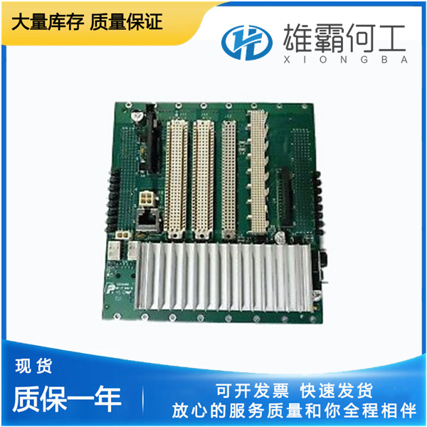
LAM 810-017031-004 输入输出
产品概述:
810-017031-004状态–低压水堆STDB通过机组处于低功率备用模式的一般指示,具体情况参见状态错误停机选项卡。服务:位置控制位置控制选项卡页包含位置控制信息。位置需求(%)-根据装置配置,以用户校准范围的百分比表示实际位置需求信号。实际位置(%)-实际驱动轴输出位置的指示,以用户校准范围的百分比表示。810-017031-004实际位置N(deg)-相对于绝对轴位置,实际驱动轴输出位置的指示,以旋转度为单位。810-017031-004对于I型至IV型,逆时针全方位为零度,顺时针全方位为75度

实际电流(A)-从驱动器到执行器的实际电流指示(安培)。810-017031-004位置需求误差(%)-以用户校准范围的百分比表示需求位置和实际位置之间的差异。根据内部模型过滤此错误,以防止意外报警指示(请参阅位置错误报警)。主要需求(%)-主要位置需求信号的指示,基于装置配置,以用户校准范围的百分比表示。810-017031-004如果主需求信号失败,则此参数停止更新。备用需求(%)-根据装置配置,以用户校准范围的百分比表示备用位置需求信号。810-017031-004如果备份需求信号失败,则此参数停止更新。主控制–如果主需求是选定的需求信号,则控制指示为真。主要需求信号状态的主要故障指示。True表示失败的值。

Auto Status—String indication of the automatic user stop procedure. –1= Failed 0 = Disabled 1 = Enabled 2 = Looking for Min Stop 3 = Looking for Max Stop 4 = Stops Set Auto Status Int—Integer indication of the Auto Status string (see above).810-017031-004 Manual Enable dflt = false Command to enable the manual user calibration. When true, the Manual Set Position (%) is actively controlling the driver output to the commanded position. This mode can also be used to stroke the output. Manual Set Position (%) default 50 % (–10 to 110) Manual position demand. This demand setting is active when the Manual Mode is enabled. Can be used to both set the stops and to stroke the actuator output.810-017031-004 Manual Status—String indication of the manual user stop procedure. –1= Failed 0 = Disabled 1 = Enabled 2 = Min Stop Set 3 = Max Stop Set Manual Status Int—Integer indication of the Manual Status string (see above).810-017031-004 Manual—At Min Posn dflt = false (momentary true command only) Command to indicate minimum position is reached. This sets the 0 % (min) position for all position demand signals. Manual—At Max Posn dflt = false (momentary true command only) Command to indicate maximum position is reached. This sets the 100 % (max) position for all position demand signals. Adjusting and Testing Actuator Dynamics Actuator dynamics are set in the Configure Mode,810-017031-004 but can also be adjusted in the Adjust User Stop mode. There is only one adjustable dynamics parameter, it is the Actuator Inertia Setting (see Table 9-1).

Mode Int—Integer indication of the mode string (see above). ProAct Software Version—Displays the version number of the software installed.810-017031-004 Config ID—Displays the identification of the software system configurables. The default for this parameter is ProAct Digital Plus Configuration, however this string can be edited in the CFG file to a more meaningful name relative to the specific application setup and then downloaded back into the ProAct control.810-017031-004 CAN ProAct Number—Indication of the identification number used in the CAN communication. Based on the status of the CAN ID Hi and Lo discrete inputs at power-up. Elect Temp (°C)—Indication of the detected electronics temperature in degrees Celsius. RunTime–Clear Command—Command to clear the accumulated RunTime. RunTime–Hours—Accumulated runtime hours since the last Run Time Clear command was issued.810-017031-004 Time accumulates whenever the unit is powered up and is stored on an hourly basis or if the Low Power Standby Mode discrete input is enabled. RunTime–100mSec—Accumulated runtime in units of 100 ms (36 000 in an hour). Resets to zero on a power-up or Clear command. Time accumulates whenever the unit is powered-up and is stored on an hourly basis or if the Low Power Standby Mode discrete input is enabled. Shutdown Command—Command to force the unit into a shutdown condition using the Service Tool.810-017031-004 Helpful for entering into modes that require the unit to be shut down, like Configure or Adjust User Stops.

This command can be toggled between true and false. When toggled to true, the unit remains in a shutdown state until this parameter is set back to false or the power is cycled on the ProAct810-017031-004. Status–Alarm—General indication that an alarm condition exists, refer to the Status Error—Alarms tab sheet for the specific alarm condition. Status–Shutdown—General indication that a Shutdown condition exists, refer to the Status Error—Shutdowns tab sheet for the specific condition.810-017031-004 Status–Low Pwr Stdby—General indication that the unit is in Low Power Standby Mode, refer to the Status Error—Shutdowns tab sheet for the specific condition. Service: Position Control The Position Control tab sheet contains position control information. Position Demand (%)—Indication of the actual position demand signal, based on unit configuration, in percentage of the user calibrated range.810-017031-004 Actual Posn (%)—Indication of the actual driver shaft output position, in percentage of the user calibrated range. Actual Posn (deg)—Indication of the actual driver shaft output position, in degrees rotation, relative to absolute shaft position.810-017031-004 For models I through IV, full counterclockwise is zero degrees and full clockwise is 75 degrees


