
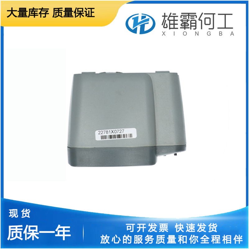
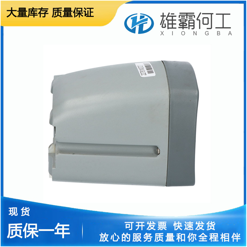
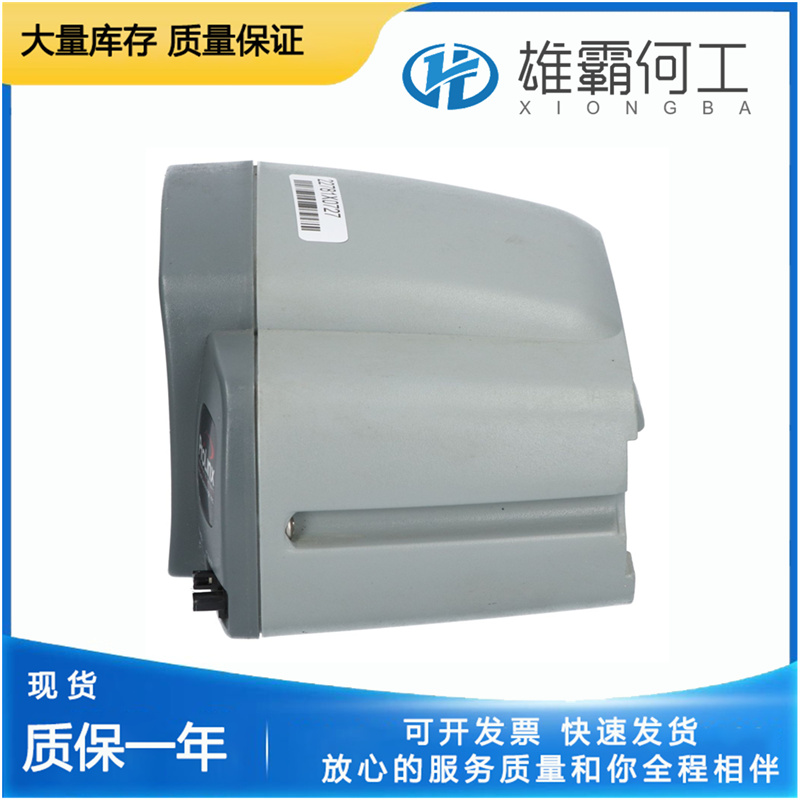
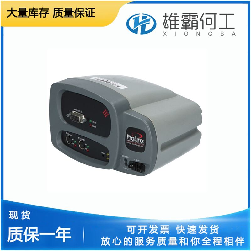
PROSOFT 3100-MCM 通信接口模块
安装要求UG杠杆调速器的推荐转速范围为375至1500 rpm,可顺时针或逆时针驱动。建议的最大恒定转速为1000至1500转/分,在额定转速和正常工作温度下需要1/3马力(249瓦)。工作温度范围为-40至+220°F(-40至+104°C)。安装调速器之前,确保调速器驱动轴能够自由旋转。使用调速器和原动机驱动器之间正确长度的联轴器,将调速器垂直安装并固定在其安装垫上。确保传动轴没有卡滞、侧面负载过大或联轴器没有松动。不得有任何力将驱动轴推入调速器。h允许发动机通过节气门关闭
任何零件之间的对齐不当或配合过紧都可能导致零件过度磨损或卡住。它还可能导致调速器输出轴出现不希望有的高频振动或“抖动”。(更多信息请参见第5章中的定义)。UG调速器与发动机驱动垫平齐安装。如果发动机驱动垫成一定角度(最大0°至45°),则安装UG调速器时必须使前面板处于上部位置。在调速器和发动机驱动垫之间使用垫圈,以允许出现表面缺陷。确保调速器周围有足够的可用空间,以便安装控制连杆、向调速器加油以及调整速度和补偿系统。安装孔尺寸和调速器尺寸见外形图,图1-3。标准的UG调速器锯齿形驱动器几乎没有安装问题。然而,必须保持轴与驱动联轴器的同心度,联轴器应尽可能长,以允许更大的灵活性和更长的寿命。
The standard UG Governor serrated drive offers few installation problems. However, the concentricity of the shaft to the drive coupling must be maintained, and the coupling should be as long as possible to permit greater flexibility and a longer life. A misalignment of the drive shaft can result in a broken drive shaft, causing an overspeed condition or runaway engine. An overspeeding or runaway engine can result in extensive damage to the equipment, personal injury, and/or loss of life. If an optional keyed drive is used when installing the governor, take care to avoid the following undesirable conditions: • Rough gear teeth Rough gear teeth or shaft out of round, can cause vibrations which can be transmitted to the governor and cause a jiggle in the governor output shaft. The jiggle can be transmitted to the fuel control, resulting in an undesirable condition. Replace gears if necessary.

Improper alignment or too tight a fit between any of the parts can result in excessive wear or seizure of parts. It can also cause an undesirable high frequency vibration or “jiggle” in the governor output shaft. (See Definitions in Chapter 5 for more information). The UG Governor is mounted flush with the engine drive pad. If the engine drive pad is at an angle (from 0 to 45° maximum), the UG Governor must be installed with the front panel in the upper position. Use a gasket between governor and engine drive pad to allow for surface imperfections. Be sure there is adequate space available around the governor to provide easy access for installing the control linkage, filling the governor with oil, and adjusting the speed and compensation system. See Outline Drawing, Figure 1-3, for mounting hole sizes and governor dimensions.

Mounting Requirements The recommended speed range for the UG Lever governor is 375 to 1500 rpm and can be driven clockwise or counterclockwise. The recommended maximum constant speed is 1000 to 1500 rpm, requiring 1/3 hp (249 W) at rated speed and normal operating temperature. Operating temperature range is –40 to +220 °F (–40 to +104 °C). Make sure the governor drive shaft rotates freely before installing the governor. Mount and fasten the governor squarely on its mounting pad using the correct length of coupling between the governor and the prime mover drive. Be sure there is no binding, excessive side loading of the drive shaft, or looseness in the coupling. There must be no force pushing the drive shaft into the governor.h allows the engine to be shut down from the throttle