
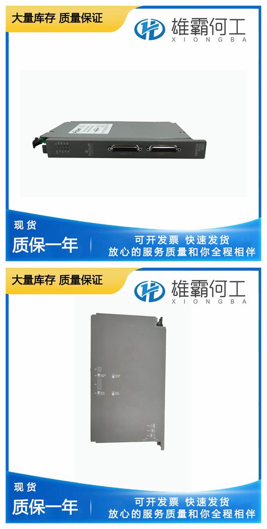
PROSOFT 5301-MBP-DFCM 通用串行
泵从独立式油底壳(13)中获取油。油泵是一个容积式齿轮泵,具有四个单向阀(11),用于任一旋转方向。一个泵齿轮是旋转衬套(15)的一部分,另一个是叠层驱动器(19)的一个。旋转衬套(15)由调速器驱动轴(17)驱动,调速器驱动轴由原动机驱动。当衬套(15)旋转时,它使层压驱动器(19)旋转。油泵齿轮(12)可以顺时针或逆时针驱动。油流通过单向阀系统(11)流入蓄能器系统(8)。蓄能器蓄能器(8)的用途是在压力下储存油,以便操作UG杆调速器。如果机油压力增加到120磅/平方英寸/827千帕(对于UG-10为150磅/平方毫米/1034千帕)以上,蓄能器(两个气缸)也起到减压阀的作用。蓄能器(8)由两个弹簧加载的活塞(9)组成。机油被泵入油缸,压力随着蓄能器弹簧(9)的压缩而增加。当油压超过120 psi/827 kPa(对于UG-10为150 psi/1034 kPa)时,机油通过每个气缸中的泄压口(10)流回油底壳。机油从蓄能器(8)经过油道流向动力活塞(7)顶部和先导阀系统(14和15)
建议机油的连续工作温度为140至200°F(60至93°C)。环境温度限制为–20至+200°F(–29至+93°C)。测量壳体外部下部调速器的温度。实际机油温度将稍微升高,大约升高10°F(6°C)。遵循制造商关于溶剂使用的说明或限制。如果没有可用的说明,请小心处理。在通风良好、远离火源或火花的地方使用清洁溶剂。不遵守上述安全说明可能导致危险火灾、设备大面积损坏、人身伤害和/或生命损失。简介UG杠杆调速器的基本操作适用于所有类型。唯一的区别在于设置速度的方法。辅助装置提供不同的功能,但不会改变调速器的基本操作。与正文一起提供的是示意图,如图3-1所示。提供了直观的方式来理解UG杠杆调速器的操作。部件描述在开始UG杠杆调速器的操作之前,对部件的简要描述将有助于理解操作。油泵油泵(12)的作用是为调速器提供油压。
Accumulator The purpose of the accumulator (8) Is to store oil under pressure for the operation of the UG Lever governor. The accumulator (two cylinders) also acts as a pressure relief valve if oil pressure is increased above 120 psi/827 kPa (150 psi/1034 kPa for UG-10). The accumulator (8) consists of two spring-loaded pistons (9). Oil is pumped into the cylinders and pressure is increased as the accumulator springs (9) are compressed. When the oil pressure exceeds 120 psi/827 kPa (150 psi/1034 kPa for UG-10), oil is released back to sump through a relief port (10) in each cylinder. Oil flows from the accumulator (8) through passages to the top of the power piston (7) and to the pilot valve system (14 and 15)
is provided for visual means of understanding the operation of the UG Lever governor. Component Description Before getting into the operation of the UG Lever governor, a brief description of the components will facilitate understanding the operation. Oil Pump The purpose of the oil pump (12) is to provide oil pressure for the governor. The pump gets its oil from the self-contained sump (13). The oil pump is a positive displacement gear pump with four check valves (11) for either direction of rotation. One pump gear is part of the rotating bushing (15), and the other is part of the laminated drive (19). The rotating bushing (15) is driven by the governor drive shaft (17) which is driven by the prime mover. As the bushing (15) rotates, it rotates the laminated drive (19). The oil pump gears (12) can be driven either clockwise or counterclockwise. Oil flow is directed through the check valve system (11) into the accumulator system (8).
The recommended continuous operating temperature of the oil is 140 to 200 °F (60 to 93 °C). The ambient temperature limits are –20 to +200 °F (–29 to +93 °C). Measure the temperature of the governor on the outside lower part of the case. The actual oil temperature will be slightly warmer, by approximately 10 °F (6 °C). Follow the manufacturer’s instructions or restrictions regarding the use of solvents. If no instructions are available, handle with care. Use the cleaning solvent in a well ventilated area away from fires or sparks. Failure to follow the above safety instructions can result in dangerous fires, extensive damage to equipment, personal injury, and/or loss of life.Introduction Basic UG Lever Governor operation is similar for all types. The only difference is in the method of setting the speed. Auxiliary devices provide different functions but do not alter the basic operation of the governor. Along with the text, a schematic diagram, Figure 3-1.