
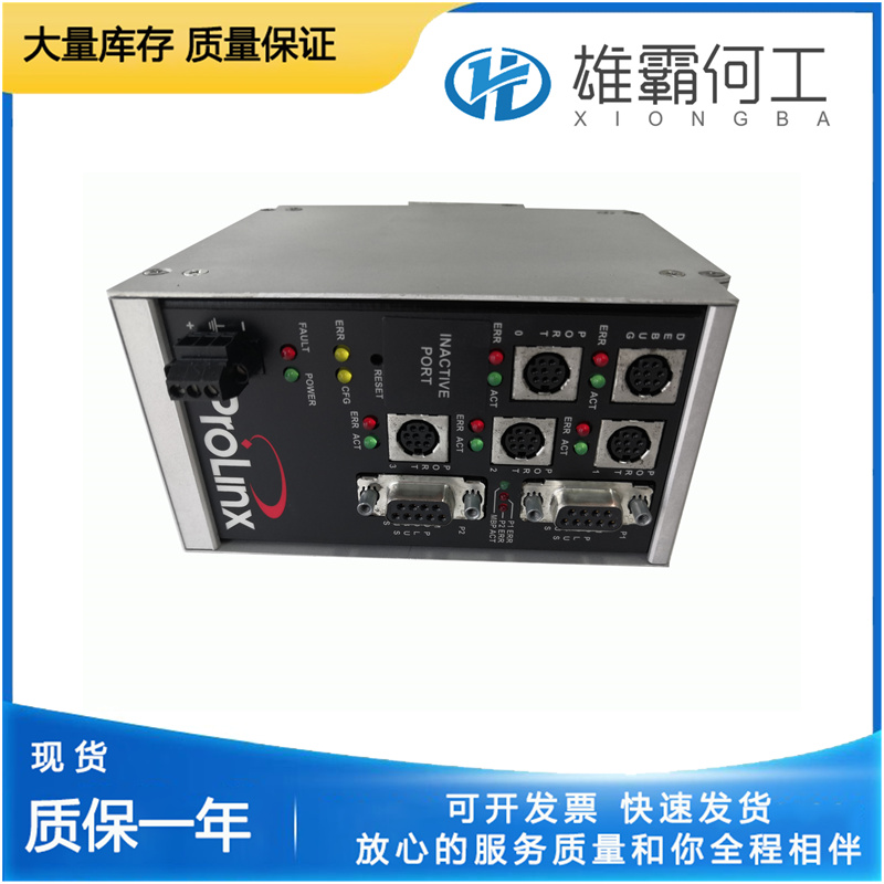
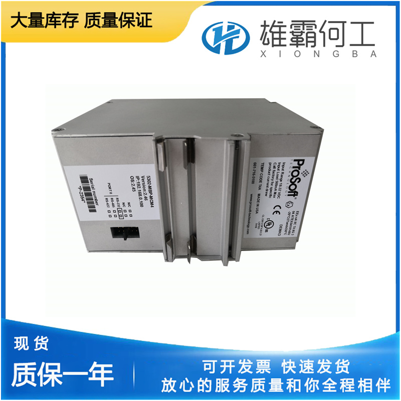
PROSOFT 5302-MBP-MCM4 网络通讯模块
球头系统球头系统(3)的目的是与调速器弹簧(26)给出的速度设定基准相比,感应原动机的速度变化,并定位先导阀柱塞(14)。球头系统由球头(3)、飞锤(2)、调速器弹簧(26)、止推轴承(25)、调速器塞(1)和调速器杆(4)组成。球头(3)是齿轮传动的,并由层压驱动器(19)驱动。飞锤(2)通过枢轴销连接到球头(3)上。推力轴承(25)位于飞锤(2)的趾部上。调速器弹簧(26)由调速器螺塞(1)固定在止推轴承(25)上。当球头(3)旋转时,由于离心力的作用,飞锤(2)向外枢转。同时,调速器弹簧(26)迫使止推轴承(25)向下作用在飞锤脚趾(2)上。这个向下的力与飞锤(2)的离心力相反。增加驱动速度会增加离心力。用调速器塞(1)压缩调速器弹簧(26)会增加向下的力,进而增加调速器转速设定值。原动机必须运行得更快,才能产生更高的离心力,以克服调速器弹簧力并重新平衡系统。调速器弹簧力或速度设置通过速度调节轴(1)手动控制。补偿系统补偿系统的目的是使调速器稳定,并获得稳定的速度控制。此外,当正确调节时,补偿系统有效地调节使发动机达到所需输出所需的燃油量,以调节负载的减少或增加。大补偿活塞(21)、小补偿活塞(20)、浮动杆(18)、带可调节支点(24)的补偿调节杆(5)以及补偿针阀(22)组成补偿系统(见图3-1)。补偿只是暂时速度下降特性的另一个词。补偿系统引入了随输出轴运动而对速度设置进行的临时重新调整,以产生稳定的速度下降特性,随后速度设置相对缓慢地恢复到其原始值。
动力活塞动力活塞(7)的作用是将调速器输出轴旋转到增加或减少燃油的位置。动力活塞(伺服)是一种差动式,活塞两侧都有油压。活塞的上端通过动力杆和连杆总成连接到调速器输出轴(6)上。动力活塞(7)的底部的面积比活塞的顶部大。因此,与顶部相比,底部需要更小的油压来保持活塞静止。如果活塞顶部和底部的油压相同,则向上移动活塞,使终端轴沿增加燃油的方向旋转。只有当活塞下方的机油释放到油底壳时,活塞才会向下移动。进出动力活塞底部的机油由先导阀系统调节。先导阀系统先导阀系统(14和15)的作用是控制流向或来自动力活塞(7)底部的油流量。衬套(15)由驱动轴(17)旋转,通过这种旋转,先导阀柱塞和衬套之间的摩擦减小。先导阀柱塞(14)具有一个控制平台,用于调节通过衬套(15)中端口的油流量。当pvp(14)下降时,高压油在动力活塞(7)下方流动,使其上升。当pvp上升时,油从动力活塞下方释放到油底壳,使其下降。活塞(7。当pvp(14)处于其中心位置时,控制平台覆盖控制端口,如示意图所示(图3-1),并且动力活塞没有移动。pvp运动由球头系统(3)和小型和大型补偿活塞(20和21)控制。
Accumulator The purpose of the accumulator (8) Is to store oil under pressure for the operation of the UG Lever governor. The accumulator (two cylinders) also acts as a pressure relief valve if oil pressure is increased above 120 psi/827 kPa (150 psi/1034 kPa for UG-10). The accumulator (8) consists of two spring-loaded pistons (9). Oil is pumped into the cylinders and pressure is increased as the accumulator springs (9) are compressed. When the oil pressure exceeds 120 psi/827 kPa (150 psi/1034 kPa for UG-10), oil is released back to sump through a relief port (10) in each cylinder. Oil flows from the accumulator (8) through passages to the top of the power piston (7) and to the pilot valve system (14 and 15)
The ballhead system consists of a ballhead (3), flyweights (2), speeder spring (26), thrust bearing (25), speeder plug (1), and speeder rod (4). The ballhead (3) is geared and is driven by the laminated drive (19). The flyweights (2) are attached to the ballhead (3) with pivot pins. A thrust bearing (25) rides on the toes of the flyweights (2). The speeder spring (26) is held against the thrust bearing (25) by the speeder plug (1). As the ballhead (3) rotates, the flyweights (2) pivot outward due to the centrifugal force. At the same time, the speeder spring (26) is forcing the thrust bearing (25) downward on the flyweight toes (2). This downward force opposes the centrifugal force of the flyweights (2). Increasing the drive speed increases the centrifugal force. Compressing the speeder spring (26) with the speeder plug (1) increases the downward force and in turn increases the governor speed setting. The prime mover must run faster to produce a higher centrifugal force to overcome the speeder spring force and rebalance the system.
Power Piston The purpose of the power piston (7) is to rotate the governor output shaft to the increase or decrease fuel position. The power piston (servo) is a differential type with oil pressure on both sides of the piston. The upper end of the piston is connected to the governor output shaft (6) through a power lever and link assembly. The bottom of the power piston (7) has a larger area than the top of the piston. Therefore, less oil pressure is required on the bottom than on the top to maintain the piston stationary. If the oil pressure is the same on both the top and bottom of the piston, the piston is moved upward to rotate the terminal shaft in the increase fuel direction. The piston moves downward only when oil under the piston is released to sump. Oil to or from the bottom of the power piston is regulated by the pilot valve system. Pilot Valve System The purpose of the pilot valve system (14 and 15) is to control the flow of oil to or from the bottom of the power piston (7).