

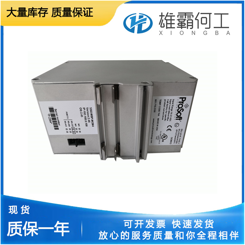

PROSOFT 5302-MBP-MCM4/MB+ PLC模块
降速UG杠杆调速器可在工厂配备降速组件。速度下降,或者简称为下降,是在调速器中产生稳定性的一种方法。Droop还用于在并联或连接到单个轴的两个或多个原动机之间分配和平衡负载。Droop是调速器输出轴响应负载增加从最小燃油位置移动到最大燃油位置时发生的速度下降,以额定速度的百分比表示。如果,而不是降低速度。出现增加时,调速器显示出负下降。负下降将导致调速器不稳定。没有足够的下垂会导致不稳定,表现为振荡、浪涌或难以响应负载变化。过多的下垂可能导致调速器在负载上下时响应缓慢。使用调速器速度在空载时为1500rpm和在满载时为1450rpm的示例,降速可通过以下公式计算:%降速=空载速度–满载速度满载速度x 100%降速=1500 rpm–1450 rpm 1450 rpm x 100=3.5%如果调速器输出轴未使用从“空载”到“满载”的全部2/3可用行程,降速也将成比例减少。如果转速下降幅度大于50 rpm,调速器显示下降幅度大于3.5%。
调速器弹簧力或速度设置通过速度调节轴(1)手动控制。补偿系统补偿系统的目的是使调速器稳定,并获得稳定的速度控制。此外,当正确调节时,补偿系统有效地调节使发动机达到所需输出所需的燃油量,以调节负载的减少或增加。大补偿活塞(21)、小补偿活塞(20)、浮动杆(18)、带可调节支点(24)的补偿调节杆(5)以及补偿针阀(22)组成补偿系统(见图3-1)。补偿只是暂时速度下降特性的另一个词。补偿系统引入了随输出轴运动而对速度设置进行的临时重新调整,以产生稳定的速度下降特性,随后速度设置相对缓慢地恢复到其原始值。大补偿活塞(21)通过补偿调节杆(5)连接到输出轴(6)。可枢转的支点(24)骑在调节杆上。改变支点的位置允许调节杆(5)控制可用于致动补偿活塞的行程量。小补偿活塞(20)通过浮动杆与先导阀柱塞和调速器杆相连。向下移动大补偿活塞(21)会迫使机油位于小补偿活塞(20)下方。当小补偿活塞(20)被向上推动时,它提升pvp以关闭控制端口,从而阻止机油流向动力活塞(7)的底部。针阀(22)控制油底壳与大补偿活塞(21)和小补偿活塞(20)之间的油流量。补偿必须根据特定的发动机和负载进行适当调整,以提供稳定的运行(见第4章,补偿调整)。
Accumulator The purpose of the accumulator (8) Is to store oil under pressure for the operation of the UG Lever governor. The accumulator (two cylinders) also acts as a pressure relief valve if oil pressure is increased above 120 psi/827 kPa (150 psi/1034 kPa for UG-10). The accumulator (8) consists of two spring-loaded pistons (9). Oil is pumped into the cylinders and pressure is increased as the accumulator springs (9) are compressed. When the oil pressure exceeds 120 psi/827 kPa (150 psi/1034 kPa for UG-10), oil is released back to sump through a relief port (10) in each cylinder. Oil flows from the accumulator (8) through passages to the top of the power piston (7) and to the pilot valve system (14 and 15)

If, instead of a decrease in speed. an increase takes place, the governor is showing a negative droop. Negative droop will cause instability in a governor. Not enough droop can cause instability in the form of hunting, surging or difficulty in response to a load change. Too much droop can result in slow governor response in picking up or dropping off a load. Using an example where the governor speed is 1500 rpm at no load and 1450 rpm at full load, droop can be calculated with the formula: % Droop = No load speed – Full load speed Full load speed x 100 % Droop = 1500 rpm – 1450 rpm 1450 rpm x 100 = 3.5% If the governor output shaft does not use the full 2/3 of available travel from “NO LOAD” to “FULL LOAD,” droop will also be reduced proportionately. If the decrease in speed is greater than 50 rpm, droop greater than 3.5% is shown by the governor.

Speeder spring force or speed setting Is controlled manually through the speed adjusting shaft (1). Compensation System The purpose of the compensation system is to give stability to the governor and to obtain steady state speed control. Also, when correctly adjusted, the compensation system effectively regulates the amount of fuel necessary to bring the engine to the required output to adjust to a decrease or an increase in load. A large compensation piston (21), small compensation piston (20), a floating lever (18), a compensation adjusting lever (5) with adjustable fulcrum (24), along with a compensating needle valve (22) make up the compensation system (see Figure 3-1). Compensation is simply another word for temporary speed droop characteristic. The compensation system introduces a temporary readjustment of speed setting with output shaft movement to produce a stabilizing speed droop characteristic, followed by a relatively slow return of speed setting to its original value.The large compensation piston (21) is linked to the output shaft (6) by a compensation adjusting lever (5). A pivotable fulcrum (24) rides on the adjusting lever. Changing the fulcrum’s position allows the adjusting lever (5) to control the amount of stroke available for the actuating compensating piston.