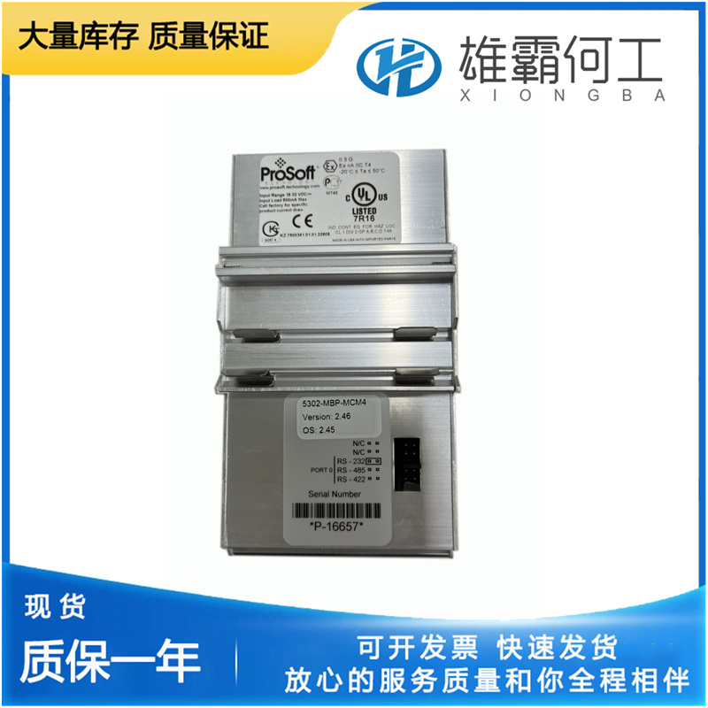
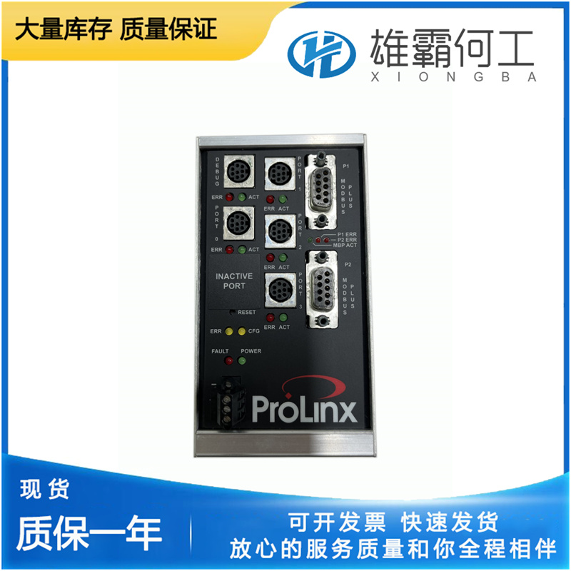
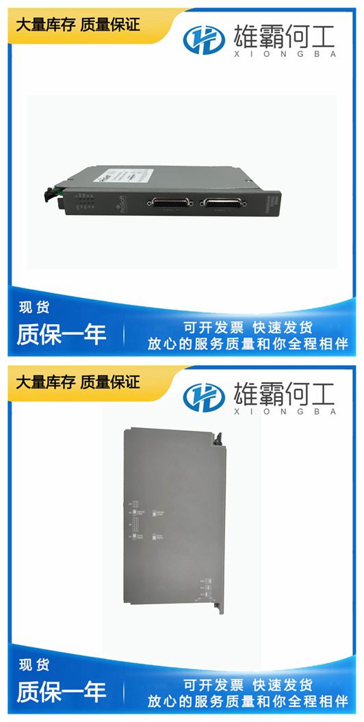
PROSOFT 5304-MBP-PDPM 模拟量输入卡
允许动力活塞下的机油流向油底壳。动力油缸顶部的油压迫使动力活塞下降到零燃油位置。如果正确调整了与发动机的连杆,发动机将关闭。5304-MBP-PDPM,以更好地了解UG杠杆调速器的操作。本原理图为基本设计,不包括任何辅助设备。本说明基于负荷变化引起的速度变化。但是,如果通过重新定位速度控制连杆来更改调速器速度设置,则会发生相同的调速器移动顺序。负载降低假设原动机以一定速度运行。5304-MBP-PDPM飞锤处于垂直位置,用于正常稳态操作。先导阀柱塞(14)的控制平台位于旋转衬套(15)的控制端口的中心。这会阻止压力油流过衬套(15)控制端口。因此,动力活塞(7)和调速器输出轴(6)都不会移动。

如果转速下降小于50 rpm,调速器显示下降小于3.5%。当调速器输出轴(5)移动以增加燃油时,转速设定值弹簧压缩减小,从而降低调速器转速设定值。当施加负载时,机组开始减速。当调速器输出轴(5)移动以减少燃油时,转速设定弹簧压缩增加,从而增加调速器转速设定。随着负载的降低,机组开始提高速度。当负载增加或减少时,调速器速度设置的这种变化有助于调速器在机组与其他机组机械连接时抵抗负载变化。速降组件(图3-2)由速降杆组件、速降凸轮和速降连杆组件组成,设置后,当调速器输出轴旋转时,速降连杆会改变速度设定弹簧的压缩。有关可选降速组件的图示零件和零件参考号,请参见图6-1.如果希望从节气门位置关闭发动机,5304-MBP-PDPM杠杆调速器可以配备一个停机杆(5304-MBP-PDPM),操作如下:当节气门朝着停机位置移动时,加速塞上升,接触停机杆上的螺母。进一步移动会提升停机杆、提升调速器杆和浮动杆的内端,从而提升先导阀柱塞并打开先导阀衬套中的控制端口。
If the linkage to engine is correctly adjusted, the engine will shut down.efer to Figure 3-1 with the text to better understand the operation of the UG Lever governor. This schematic diagram is of a basic design and does not include any auxiliary equipment. This description is based on speed changes resulting from load changes. However, the same sequence of governor movements would occur if the governor speed setting were changed by repositioning the speed control linkage. Decrease in Load Assume the prime mover is running on-speed. The flyweights are in a vertical position for normal steady-state operation. The control land of the pilot valve plunger (14) is centered over the control port of the rotating bushing (5304-MBP-PDPM). This stops the flow of pressure oil through the bushing (15) control port. As a result, there is no movement of the power piston (7) and no movement of the governor output shaft (6).
The speed droop assembly (Figure 3-2) consists of a speed droop lever assembly, a speed droop cam, and a speed droop link assembly which, when set, changes the compression of the speed setting spring as the governor output shaft rotates. For illustrated parts and part reference numbers of the optional speed droop assembly, see Figure 6-1.If it is desired that the engine be shut down from the throttle position, the UG Lever governor can be equipped with a shutdown rod (Figure 3-3) operating as follows: When the throttle is moved toward the shutdown position, the speeder plug rises, contacting the nut on the shutdown rod. Further movement lifts the shutdown rod, lifting speeder rod and inner end of floating lever, thus raising the pilot valve plunger and uncovering the control port in the pilot valve bushing. This permits oil under the power piston to flow to sump. Oil pressure on top of the power cylinder forces the power piston down to the zero fuel position.

lf the decrease in speed is less than 50 rpm, droop less than 3.5% is shown by the governor. As the governor output shaft (5) moves to increase fuel, the speed setting spring compression is reduced, which reduces the governor speed setting. The unit starts reducing its speed as load is applied. When the governor output shaft (5) moves to decrease fuel, the speed setting spring compression is increased, which increases the governor speed setting. The unit starts increasing its speed as load is decreased. This change of governor speed setting when load is increased or decreased helps the governor resist a load change when the unit is connected mechanically with other units.

