
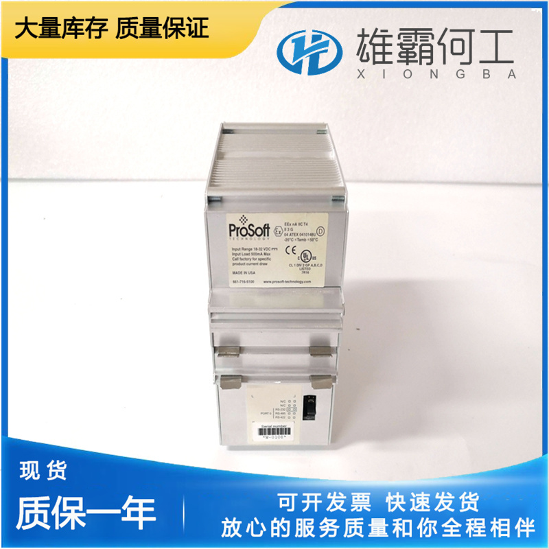
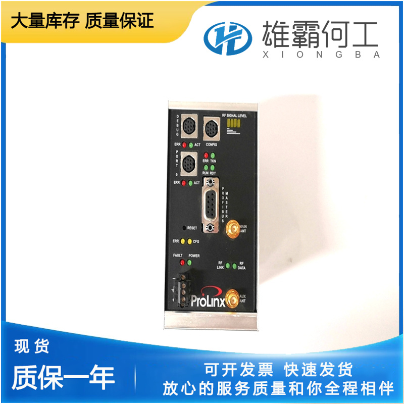
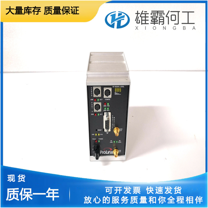
PROSOFT 6104-WA-PDPM 无线网关模块
这使先导阀衬套(15)中的控制端口被pvp(14)上的平台覆盖。10.输出轴(6)和动力活塞(7)的运动停止在新的燃料减少位置,该位置是在负载减少的情况下以选定的速度设置运行原动机所需的。再次增加负载,假设原动机以一定速度运行。飞锤处于垂直位置,先导阀柱塞居中。当负载增加并保持相同的燃油设定值时,负载增加会导致速度下降。这将生成以下调速器运动序列:1。随着速度的降低,飞锤(2)的离心力减小,并且反向的减速器弹簧(26)的力现在大于飞锤(1)的离心作用力。2.飞锤(2)向内倾斜,降低调速器杆(4)和浮动杆(18)的右端。3.这降低了先导阀柱塞(14),打开了旋转衬套(15)中的控制端口。压力油通过控制端口释放到动力活塞(7)的底部。
当负载减少并且保持相同的燃油设定值时,负载减少会导致速度增加。这会产生以下动作序列:1。随着速度的增加,飞锤(2)的离心力增加,克服了相反的调速器弹簧力。2.飞锤(2)向外倾斜,升起调速器杆(4)和浮动杆(18)的右端。3.这将升高先导阀柱塞(pvp)(14),打开旋转衬套(15)中的控制端口。机油从动力活塞(7)的底部释放到油底壳。4.作用在动力活塞(7)顶侧的压力油迫使其向下,并使输出轴(6)沿减少燃料的方向旋转。5.来自输出轴(6)的连杆降低补偿调节杆(5),补偿调节杆在支点(24)处枢转,抬起大补偿活塞(21)。6.因此,对小补偿活塞(20)的腔室施加吸力,从而降低浮动杆(18)的左端。7.依次降低pvp(14),关闭控制端口(16)。8.当油底壳油从油底壳流经针阀(22)进入补偿活塞组件(20和21)时,补偿弹簧以与调速器杆(4)相同的速率将小缓冲器补偿活塞(21)返回到其正常居中位置。这将使先导阀柱塞(14)保持在其中心位置。
Increase in Load Again, assume the prime mover is running on-speed. The flyweights are in a vertical position and the pilot valve plunger is centered. When an increase in load occurs and the same fuel setting is maintained, an increase in load creates a decrease in speed. This generates the following sequence of governor movements: 1. As speed decreases, the centrifugal force of the flyweights (2) decreases and the opposing speeder spring (26) force is now greater than the centrifugal force of the flyweights (2). 2. The flyweights (2) tip inward, lowering the speeder rod (4) and the right end of the floating lever (18). 3. This lowers the pilot valve plunger (14) opening the control port in the rotating bushing (15). Pressure oil is released through the control port to the bottom side of the power piston (7).
Suction is thus applied to the chamber of the small compensation piston (20), lowering the left end of the floating lever (18). 7. The pvp (14) is lowered in turn, closing off the control port (16). 8. As sump oil flows through the needle valve (22) from the sump into the compensation piston assembly (20 and 21), the small dashpot compensation piston (21) is returned to its normal centered position by the compensation spring at the same rate as the speeder rod (4). This keeps the pilot valve plunger (14) in its centered position. 9. This keeps the control port in the pilot valve bushing (15) covered by the land on the pvp (14). 10. The output shaft (6) and power piston (7) movement is stopped in the new decrease fuel position required to run the prime mover at the selected speed setting with the decrease in load.
When a decrease in load occurs and the same fuel setting is maintained, a decrease in load creates an increase in speed. This generates the following sequence of movements: 1. As speed increases, the centrifugal force of the flyweights (2) increases, overcoming the opposing speeder spring force. 2. The flyweights (2) tip outward, raising the speeder rod (4) and the right end of the floating lever (18). 3. This raises the pilot valve plunger (pvp) (14), opening the control port in the rotating bushing (15). Oil is released from the bottom of the power piston (7) to sump. 4. The pressure oil acting on the top side of the power piston (7) forces it down and rotates the output shaft (6) in the decrease fuel direction. 5. Linkage from the output shaft (6) lowers the compensation adjusting lever (5) which pivots at the fulcrum (24), lifting up the large compensation piston (21).