
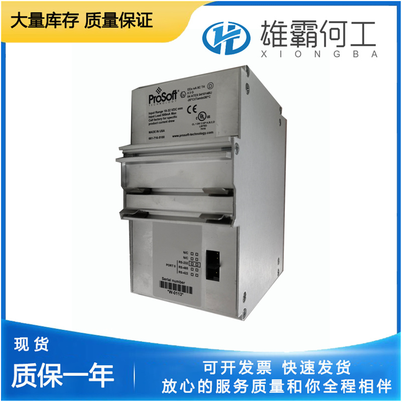
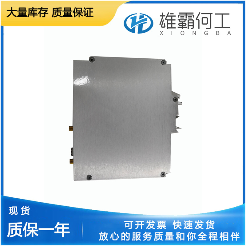
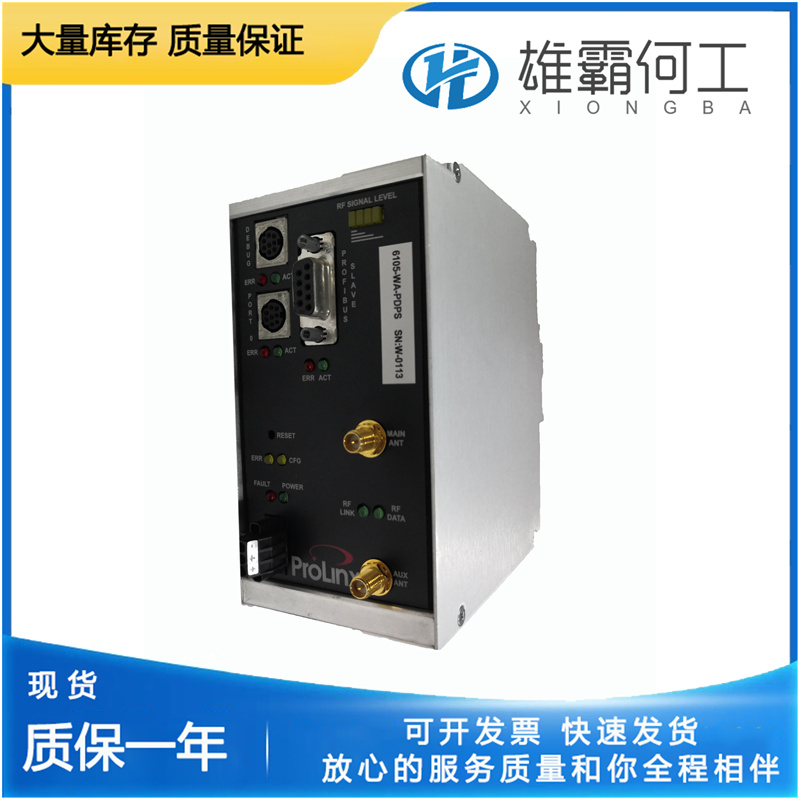
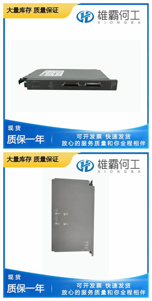
PROSOFT 6105-WA-PDPS 通讯模块
在UG杠杆调速器的初始操作之前,检查之前的所有安装步骤是否已成功完成,所有连杆是否牢固、布置和连接是否正确(见第2章)。也请阅读本章的全部内容。将调速器加油至油视镜上的顶部标记。6105-WA-PDPS 小心地(顺时针)关闭针阀,然后将其打开1/2到3/4圈。松开固定补偿调整指针的螺母,使其足以移动指针,并将指针设置在刻度的中间。拧紧螺母。如果更换调速器,6105-WA-PDPS 初始补偿设置可以是刚刚拆下的调速器的补偿设置。启动发动机、涡轮机或其他类型的原动机时,要做好紧急停机的准备,以防止失控或超速,从而可能造成人身伤害、生命损失或财产损失。按照原动机制造商的说明启动原动机。调整通常情况下,将新调速器投入使用的唯一调整是排出滞留空气并调整补偿,以获得令人满意的稳定性和响应。所有其他操作调整都是在工厂测试期间根据原动机制造商的规范进行的,不需要进一步调整。本手册的“发动机测试程序”部分给出了转速下降、高速和低速停止以及停机螺母调整。除非您完全熟悉正确的程序,否则不要尝试对调速器进行内部调整。补偿调整针阀和调整指针是补偿系统的可调整部件。它们的设置直接影响调速器的稳定性6105-WA-PDPS 。补偿必须根据特定的发动机和负载进行适当调整,以提供稳定的运行。
作用在动力活塞底侧的压力油迫使其向上,并使输出轴沿增加燃油的方向旋转。5.来自输出轴(6)的连杆升高补偿调节杆(5),补偿调节杆在支点(24)处枢转,从而降低大补偿活塞(21)。6.压力油被施加到小补偿活塞(20)的腔室中,从而升起浮动杆(18)的左端。7.依次升高pvp,关闭控制端口(18)。8.当油底壳油从缓冲器补偿活塞总成(20和21)流经针阀(22)时,补偿弹簧以与调速器杆(4)相同的速率将小补偿活塞(20)返回到其正常居中位置。这将使先导阀柱塞(14)保持在其中心位置。9.这使先导阀衬套(15)中的控制端口被pvp(14)上的平台覆盖。10.输出轴(6)和动力活塞(7)的运动停止在新的增加燃料位置,该位置是在负载增加的情况下以选定的速度设置运行原动机所需的。在负载减少或增加的任何一种情况下,补偿系统都以相同的方式运行:大补偿活塞的补偿或移动量由补偿调节(支点位置)控制。小补偿活塞(20)恢复正常的速率由针阀(22)的调节来控制,即通过针阀的油流量。如果调整正确,补偿系统将有效地调节使发动机达到所需输出所需的燃油量,以适应负载的减少或增加或速度设置的变化。
Fill the governor with oil to the top mark on the oil sight glass. Close the needle valve carefully (clockwise), then open it 1/2 to 3/4 turn. Loosen the nut holding the compensation adjusting pointer enough to move the pointer and set the pointer in the middle of the scale. Tighten the nut. If replacing a governor, the initial compensation setting can be that of the governor just removed. Be prepared to make an emergency shutdown when starting the engine, turbine, or other type of prime mover, to protect against runaway or overspeed with possible personal injury, loss of life, or property damage. Follow the prime mover manufacturer’s instructions to start the prime mover. Adjustments Normally, the only adjustments for putting a new governor into service are bleeding trapped air and adjusting compensation to obtain satisfactory stability and response. All other operating adjustments were made during factory testing in accordance with the prime mover manufacturer’s specifications and should not require further adjustment.
In either case, a decrease or an increase in load, the compensation system operates in the same manner: the compensation or amount of movement of the large compensation piston is controlled by the compensation adjustment (the fulcrum position). The rate at which the small compensation piston (20) is returned to normal is controlled by the needle valve (22) adjustment—the rate of flow of oil through the needle valve (22). When correctly adjusted, the compensation system effectively regulates the amount of fuel necessary to bring the engine to the required output to adjust to a decrease or an increase in load or to a speed setting change.Before initial operation of the UG Lever governor, check that all previous installation steps are successfully accomplished and all linkages are secure and properly arranged and attached (see Chapter 2). Also read all of this chapter.

The pressure oil acting on the bottom side of the power piston forces it up and rotates the output shaft in the increase fuel direction. 5. Linkage from the output shaft (6) raises the compensation adjusting lever (5) which pivots at the fulcrum (24), lowering the large compensation piston (21). 6. Pressure oil is applied to the chamber of the small compensation piston (20), raising the left end of the floating lever (18). 7. The pvp is raised in turn, closing off the control port (18). 8. As sump oil flows through the needle valve (22) from the dashpot compensation piston assembly (20 and 21), the small compensation piston (20) is returned to its normal centered position by the compensation spring at the same rate as the speeder rod (4). This keeps the pilot valve plunger (14) in its centered position. 9. This keeps the control port in the pilot valve bushing (15) covered by the land on the pvp (14). 10. The output shaft (6) and power piston (7) movement is stopped in the new increase fuel position required to run the prime mover at the selected speed setting with the increase in load.