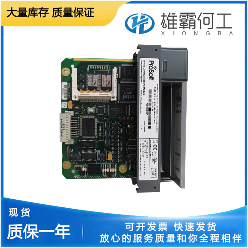
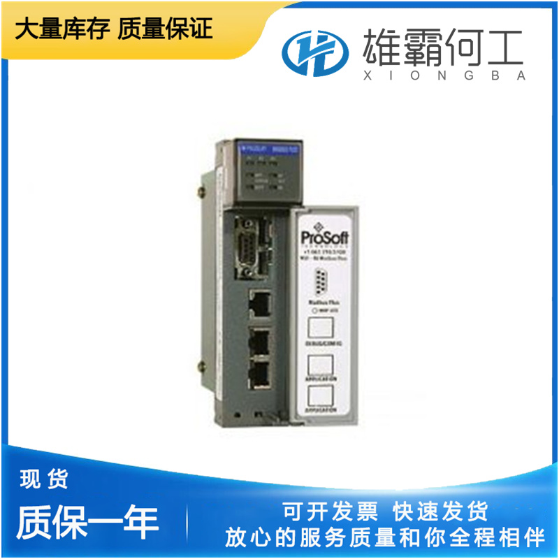
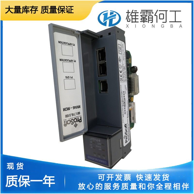
PROSOFT MVI46-GSC 通用串行
将速度设定轴移动到指定的低速设定值。将低速止动杆滑入位置,尽可能靠近上部止动螺钉(低速止动螺钉)的凸台。13.使用低速止动螺钉对低速设置进行微调(逆时针以降低速度),并用螺母(23)锁定。14.如果不需要停机,将停机螺母(30)锁在停机杆顶部。如果使用自锁螺母,将其拧到停机杆上,直到螺母上方有1/4”(6 mm)的螺纹。要将螺母设置为停机操作,请调整低速止动螺钉,使调速轴在低于最低转速设置的情况下旋转10°。将螺母向下拧到调速器螺塞的顶部,使其在低于最低转速设定值5°时停机。将螺母锁定到位。如果调速器在出厂时设置为停机,则止动杆上有一个中心冲头压痕。设置低速并调整止动杆,直到通过前盖板上的孔可以看到压痕。将螺母向下拧到调速器螺塞上,以获得停机。
如果在发动机上测试调速器,则根据制造商的说明启动原动机。运行调速器,直到达到工作温度。6.检查调速器在正常工作速度下的油压是否为110–120 psi/758–827 kPa(UG-10为135–150 psi/931–1034 kPa)。7.关闭针阀(148),并将其打开至刚好引起小的摆动。使用十字螺丝刀。如果必须使用普通螺丝刀,请确保仅使用针阀的浅槽,以避免损坏孔内的螺纹和针阀。螺纹或针阀损坏会导致调速器摆动。让原动机摆动约30秒,以排出调速器油道中的滞留空气。8.关闭针阀,再打开半圈。如果调速器继续摆动,重复步骤6。9.调整补偿制度。请参阅本章中的补偿调整。UG杠杆调速器恒定运行的最大转速为1500 rpm。10.移动速度设定轴以获得指定的高速。止动杆已安装在调速器总成的轴上。现在滑动轴锯齿上的高速止动块,使其尽可能靠近凸台和左侧止动螺钉(高速止动螺钉)。11.使用高速止动螺钉对高速设置进行微调(逆时针增加),并用螺母(23)锁定。
If shutdown is not required, lock shutdown nuts (30) together at the top of the shutdown rod. If a self-locking nut is used, thread it onto the shutdown rod until 1/4” (6 mm) of threads is above the nut. To set the nut(s) for shutdown operation, adjust the low speed stop screw to allow 10° rotation of the speed adjusting shaft below minimum speed setting. Thread the nut down on top of the speeder plug to obtain shutdown at 5° below minimum speed setting. Lock the nut in place. If the governor was factory set for shutdown, there is a center punch indentation in the stop lever. Set the low speed and adjust the stop lever until the indentation is visible through the hole in the front cover plate. Thread the nuts down onto the speeder plug to obtain shutdown.
Move the speed setting shaft to obtain the specified high speed. The stop levers have been installed on the shaft at governor assembly. Now slide the high speed stop on the shaft serration as close to the boss and the left hand side stop screw (high speed stop screw) as possible. 11. Use the high speed stop screw to make fine adjustments to the high speed setting (counterclockwise to increase) and lock with nut (23). 12. Move the speed setting shaft to the specified low speed setting. Slide the low speed stop lever into position as close to the boss of upper stop screw (low speed stop screw) as possible. 13. Use the low speed stop screw to make fine adjustments to the low speed setting (counterclockwise to decrease speed) and lock with nut (23).

If the governor is tested on the engine, start the prime mover according to the instructions from the manufacturer. Run the governor until it is at operating temperature. 6. Check that the governor has 110–120 psi/758–827 kPa (135–150 psi/931– 1034 kPa for UG-10) oil pressure at normal operating speed. 7. Close the needle valve (148) and open it just enough to cause a small hunt. Use a Phillips screwdriver. If a plain screwdriver must be used, make sure to use only the shallow slot of the needle valve to avoid damage to the threads inside the bore and to the needle valve. Damage to the threads or to the needle valve will cause the governor to hunt. Let the prime mover hunt for approximately 30 seconds to bleed trapped air from the governor oil passages. 8. Close the needle valve and open it again one-half turn. If the governor continues to hunt, repeat step 6. 9. Adjust the compensation system. See Compensation Adjustments in this chapter. Maximum speed for constant operation for the UG Lever governor is 1500 rpm.

