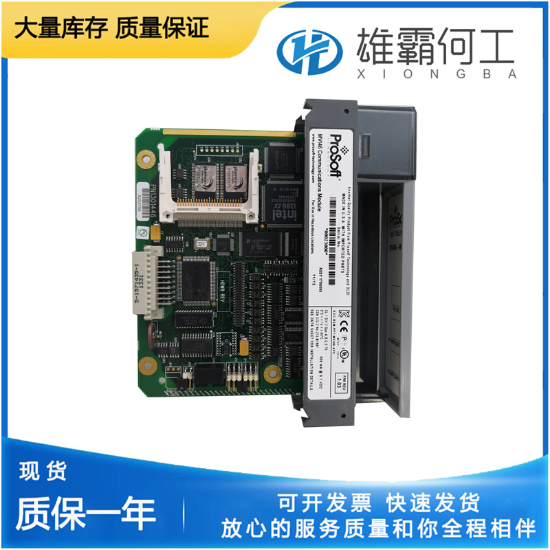
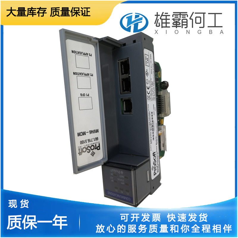
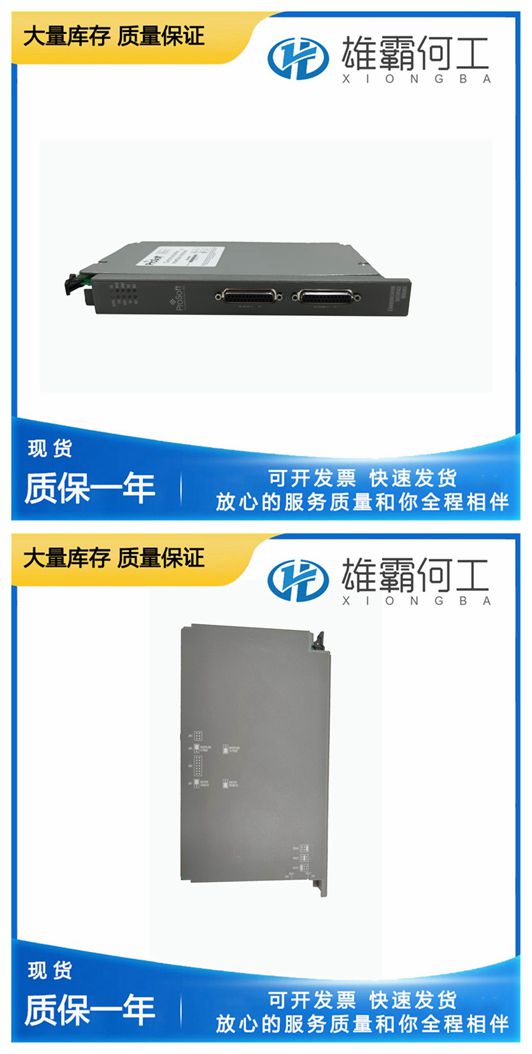
PROSOFT MVI46-MCM 网络接口模块
油位必须达到油视镜上的标记。4.将补偿调整指针设置在指针刻度的中点。5.如果在发动机上测试调速器,则根据制造商的说明启动原动机。运行调速器,直到达到工作温度。6.检查调速器在正常工作速度下的油压是否为110–120 psi/758–827 kPa(UG-10为135–150 psi/931–1034 kPa)。7.关闭针阀(148),并将其打开至刚好引起小的摆动。使用十字螺丝刀。如果必须使用普通螺丝刀,请确保仅使用针阀的浅槽,以避免损坏孔内的螺纹和针阀。螺纹或针阀损坏会导致调速器摆动。让原动机摆动约30秒,以排出调速器油道中的滞留空气。8.关闭针阀,再打开半圈。如果调速器继续摆动,重复步骤7。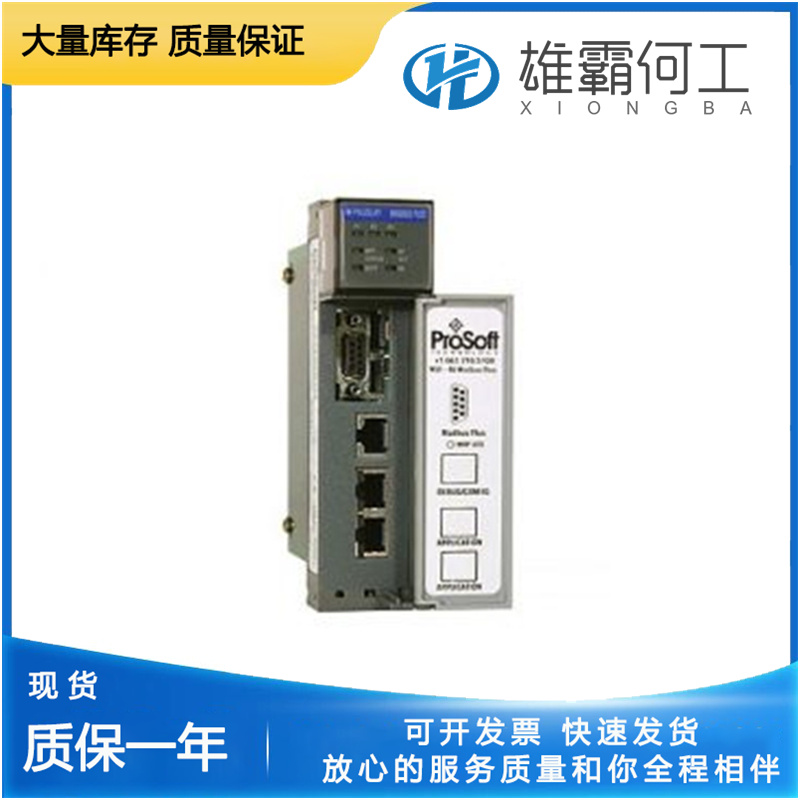
关闭发动机。拆下压力表,然后安装一个1/8“内六角管塞。在螺纹上涂抹管道密封剂,并将管塞拧紧至90 lb in(10 Nxm)。使用下垂部件进行UG操纵杆测试(参考图6-1)只有当被控制的原动机在单个装置配置中运行时,才能进行速度停止操纵杆的调整以及下垂操纵杆和凸轮调整的最终检查。此测试需要加载原动机。调整调速器,使其使用尽可能小的下垂,同时获得令人满意的控制。在难以实现最大负载的并联发电机组等应用中,观察调速器行为可能是检查下垂运行的最佳方式。在装配过程中,在下垂杆和凸轮上预设尺寸“C”,可为观测期内的原动机操作提供合理准确的下垂设置。如果在一个观察期内,该机组比其他机组承受更大的负载,则其下垂设置低于其他机组,应略微增加以更好地分担负载。1.拆下针阀塞(146)对面调速器底座上的管塞(9),并连接一个0–200 psi(0–1400 kPa)的压力表。2.将调速器安装在试验台上或发动机垫上。参见第2章。3.给调速器加油。

Run the governor until it is at operating temperature. 6. Check that the governor has 110–120 psi/758–827 kPa (135–150 psi/931– 1034 kPa for UG-10) oil pressure at normal operating speed. 7. Close the needle valve (148) and open it just enough to cause a small hunt. Use a Phillips screwdriver. If a plain screwdriver must be used, make sure to use only the shallow slot of the needle valve to avoid damage to the threads inside the bore and to the needle valve. Damage to the threads or to the needle valve will cause the governor to hunt. Let the prime mover hunt for approximately 30 seconds to bleed trapped air from the governor oil passages. 8. Close the needle valve and open it again one-half turn. If the governor continues to hunt, repeat step 7.
If, over an observation period, the unit takes greater load than the other units, its droop setting is lower than the other units and should be increased slightly for better load sharing. 1. Remove pipe plug (9) in the base of the governor on the opposite side of the needle valve plug (146) and attach a 0–200 psi (0–1400 kPa) pressure gauge. 2. Install the governor on a test stand or on the engine pad. See Chapter 2. 3. Fill the governor with oil. See Chapter 2, Oil Supply. The oil level must be to the mark on the oil sight glass. 4. Set the compensation adjusting pointer at mid-point on the pointer scale. 5. If the governor is tested on the engine, start the prime mover according to the instructions from the manufacturer.

Shut down the engine. Remove the pressure gauge and install a 1/8” socket pipe plug. Apply a pipe sealer to the threads and torque pipe plug down to 90 lb-in (10 Nxm). UG Lever Test with Droop Parts (Reference Figure 6-1) Adjustment of the speed stop levers and final check of droop lever and cam adjustment must be made only while the prime mover being controlled is operating in a single unit configuration. This test requires loading of the prime mover. Adjust the governor to use as little droop as possible yet obtain satisfactory control. On applications such as paralleled generator sets where maximum loading is difficult, observation of governor behavior may be the best way of checking droop operation. Presetting of dimension “C” on the droop lever and cam during assembly gives a reasonably accurate droop setting for prime mover operation during the observation period.

