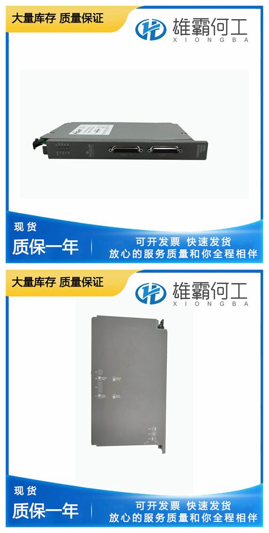
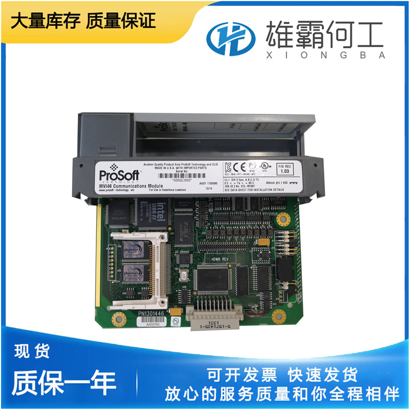
PROSOFT MVI56-ADM 带以太网
不可能预料到现场遇到的每一种麻烦。本手册涵盖了最常见的故障。调节不良可能是由于调速器性能故障,也可能是因为调速器试图纠正原动机或驱动设备的故障操作。还必须考虑任何辅助设备对调速器所需整体控制的影响。启动发动机、涡轮机或其他类型的原动机时,要做好紧急停机的准备,以防止失控或超速,从而可能造成人身伤害、生命损失或财产损失。故障诊断与排除机油在机组运行的情况下,将调速器油位保持在油视镜上的标记处。正确的油位在调速器壳体顶部以下0.75至1.25英寸(19至32毫米)处。脏油导致大多数调速器故障。使用清洁的新油或过滤过的油。使用的油容器必须完全清洁。被水污染的油会迅速分解,导致起泡并腐蚀调速器内部零件。补偿调整和针阀必须在调速器控制发动机或涡轮机的情况下正确调整补偿调整和滚针阀,即使补偿可能已在工厂或调速器测试设备上进行过调整。尽管调速器的运行可能令人满意,因为机组在无负载的情况下以恒定速度运行,但调速器仍可能无法根据其控制的负载和发动机进行正确调整。负载变化或速度设定值变化后,高过速和低欠速,或恢复速度缓慢,都是补偿调节和针阀设定值不正确的结果。定义使用以下页面上的故障排除图表(表5-2)来确定故障操作的可能原因并纠正这些故障。

调整补偿制度。请参阅本章中的补偿调整。下垂杆和凸轮(37和38)的调整会影响速度设置。因此,在进行高速和低速停止设置之前,必须检查和调整下垂。以转速为1450转/分、下降设置为3%的示例为例,移动转速设置轴,使最低燃油转速降低约1450转/分钟。UG杠杆调速器的最大推荐恒定运行速度为1500 rpm。10.将负载增加到最大值,并观察速度下降到1405 rpm。减少了3%。如果转速降至1405 rpm以下,则表示下降幅度大于3%。下垂杆和凸轮组件的尺寸“C”应略微增加。如果转速降至1405 rpm以上。指示下降小于3%。下垂杆和凸轮组件的尺寸“C”应稍微减小。降速调整正确后,设置高速和低速挡块。11.将速度设定轴移动到规定的最大速度,并施加最大负载。将轴锯齿上的高速止动杆推到尽可能靠近左侧止动螺钉(高速止动螺钉)凸台的位置。12.使用高速止动螺钉将弹齿调整到高速设置(逆时针增加),并用螺母(23)锁定。13.用最小负载将速度设定轴移动到指定的低速设定值。将低速止动杆滑入位置,尽可能靠近上部止动螺钉(低速止动螺钉)的凸台。14.使用低速止动螺钉对低速设置进行微调(逆时针方向减小),并用螺母(23)锁定。
The effect of any auxiliary equipment on the overall control required of the governor must also be considered. Be prepared to make an emergency shutdown when starting the engine, turbine, or other type of prime mover, to protect against runaway or overspeed with possible personal injury, loss of life, or property damage. Troubleshooting Oil Keep the governor oil level to the mark on the oil sight glass with the unit operating. The correct oil level is 0.75 to 1.25 inch (19 to 32 mm) below the top of the governor case. Dirty oil causes most of all governor troubles. Use clean new or filtered oil. Oil containers used must be perfectly clean. Oil contaminated with water breaks down rapidly, causing foaming and corrodes internal governor parts. Compensating Adjustment and Needle Valve The compensating adjustment and needle valve must be correctly adjusted with the governor controlling the engine or turbine,

Once the droop adjustment is correct, set the high and low speed stops. 11. Move the speed setting shaft to the maximum specified speed and apply maximum load. Push the high speed stop lever on the shaft serrations as close to the boss at the left hand stop screw (high speed stop screw) as possible. 12. Use the high speed stop screw to make tine adjustments to the high speed setting (counterclockwise to increase) and lock with nut (23). 13. Move the speed setting shaft to the specified low speed setting with minimum load. Slide the low speed stop lever into position as close to the boss of the upper stop screw (low speed stop screw) as possible. 14. Use the low speed stop screw to make fine adjustments to the low speed setting (counterclockwise to decrease) and lock with nut (23).It is impossible to anticipate every kind of trouble that Is encountered in the field. This manual covers the most common troubles experienced. Poor governing may be due to faulty governor performance, or it may be due to the governor attempting to correct for faulty operation of the prime mover or the equipment driven.

Adjust the compensation system. See Compensation Adjustments in this chapter. Adjustment of the droop lever and cam (37 and 38) affect the speed settings. For this reason, droop must be checked and adjusted before the high and low speed stop settings are made. Using an example where the speed is 1450 rpm and droop setting is 3%, move the speed setting shaft to obtain approximately 1450 rpm off minimum fuel. Maximum recommended constant operation speed for the UG Lever governor is 1500 rpm. 10. Increase load to maximum and observe a decrease in speed to 1405 rpm. which is a 3% decrease.If speed decreases below 1405 rpm, droop greater than 3% is indicated. Dimension “C” of the droop lever and cam assembly should be increased slightly. If speed decreases to more than 1405 rpm. droop less than 3% is indicated. Dimension “C” of the droop lever and cam assembly should be decreased slightly.

