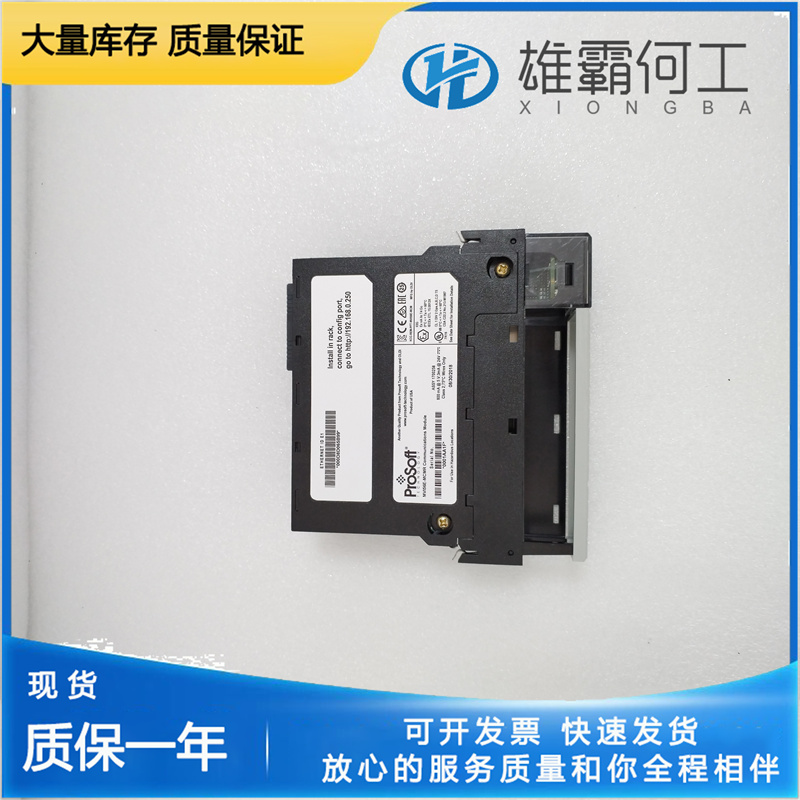
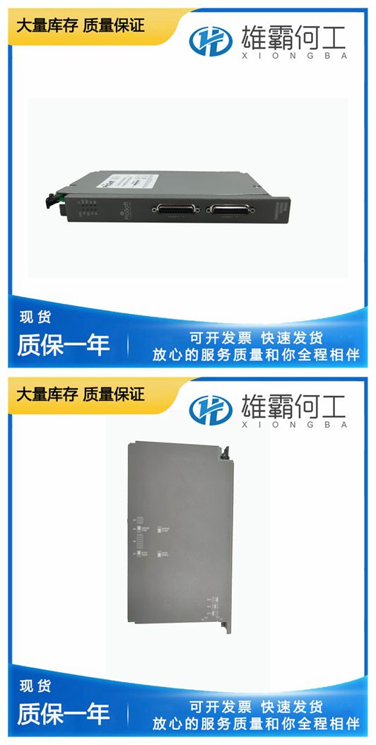
PROSOFT MVI56E-MCM 开发模块
当调速器适应这种类型的发动机时,如果连杆是线性的,则在怠速和轻负载下的操作永远不会很稳定。使调速器适应带蝶形阀的发动机的正确程序是使连杆机构,使其在轻负载下每增加一次蝶形运动,就需要比在高负载下更大的调速器运动。这种连接倾向于使发动机产生的扭矩和调速器输出轴位置之间的关系线性化(见图1-4)。下表显示了蝶阀不同开度下调速器输出轴的令人满意的角位置,以便在怠速和轻负荷下更稳定地运行。表5-1。调速器输出轴行程与蝶阀行程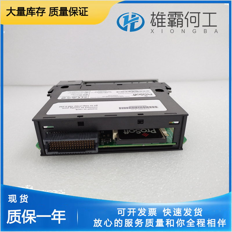
调速器空转一两分钟,然后停止发动机并排空调速器。再次冲洗调速器。给调速器重新加油(请参阅第2章“供油”)。重新启动发动机并重置补偿调整和针阀。6.检查调速器的驱动装置是否正确对齐,且没有粗糙度、侧面负载和过大的齿隙。启动发动机、涡轮机或其他类型的原动机时,要做好紧急停机的准备,以防止失控或超速,从而可能造成人身伤害、生命损失或财产损失。蒸汽轮机、燃气和汽油发动机的附加信息蒸汽轮机的发动机扭矩与节气门位置之间存在各种非线性关系。每种类型都必须使用正确的补偿连杆进行补偿,以使调速器输出轴运动与原动机扭矩输出恢复到接近线性的关系。有关正确的连杆选择和安装,请参阅原动机制造商手册。通过蝶阀控制的燃气或汽油发动机的扭矩与节气门位置的曲线总是非常非线性的。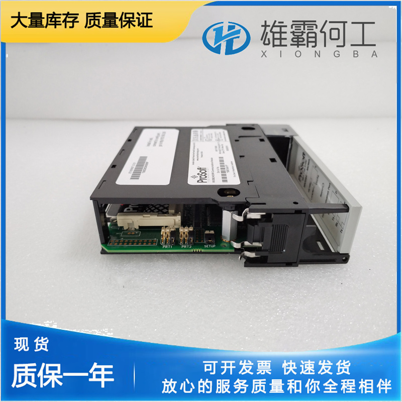
Governor Field Repairs Replacement of output shaft and drive shaft seals and bearings can be done in the field. Refer to Figures 5-1 and 5-2 and to Tables 5-3 and 5-4 for a listing of common bench tools and normal field repair tools. These tools are not considered to be essential. They do, however, make replacement of seals and bearings more convenient. Tools can be ordered from Woodward. See Chapter 8 for contact information. Include the following information: • The tool description. • The tool number or part number of the tool required. • The manual number (this is manual 03036). Removal of Governor from Engine To replace a governor on the engine, or to replace seals or bearings on the governor, remove the governor from the engine as follows: Use care in handling and resting the governor on the work area. Do not strike or rest the governor on the end of the drive shaft as damage may result to the drive shaft, oil seal, bearing, or other internal parts or surfaces. Set the governor on wooden block(s) to protect the drive shaft when performing any maintenance operation. 1. Drain oil from the governor and install the drain plug again. Some governors are equipped with a drain cock for draining. 2. Clean exterior surfaces using a cloth moistened with cleaning solvent. 3. Disconnect auxiliary device wiring and pneumatic or hydraulic tubing connections if applicable.
Please refer to the prime mover manufacturer’s handbook for the correct linkage selection and installation. The torque vs. throttle position curve for a gas or gasoline engine which is controlled through a butterfly valve is always very non-linear. When adapting a governor to this type of engine, If the linkage is made linear, operation at idle and light loads is never very stable. The proper procedure for adapting a governor to this engine with the butterfly valve is to make the linkage so that it requires greater movement of the governor per increment of butterfly movement at light loads than it does at high loads. This linkage tends to linearize the relation between engine developed torque and governor output shaft position (see Figure 1-4). The chart below shows a satisfactory angular position of the governor output shaft for different openings of the butterfly valve in order to have a more stable operation at idle and at light loads. Table 5-1. Governor Output Shaft Travel vs. Butterfly Valve Travel

Let the governor hunt for a minute or two, then stop the engine and drain the governor. Flush the governor once again. Refill the governor with oil (see Chapter 2, Oil Supply). Restart the engine and reset the compensation adjustment and needle valve. 6. Check that the drive to the governor Is correctly aligned and free of roughness, side loading, and excessive backlash. Be prepared to make an emergency shutdown when starting the engine, turbine, or other type of prime mover, to protect against runaway or overspeed with possible personal injury, loss of life, or property damage. Additional Information for Steam Turbines, Gas and Gasoline Engines The engine torque versus throttle position for a steam turbine gives a wide variety of non-linear relations. Each type must be compensated for with the correct compensating linkage to bring the governor output shaft movement back Into a near linear relation with the prime mover torque output.

