
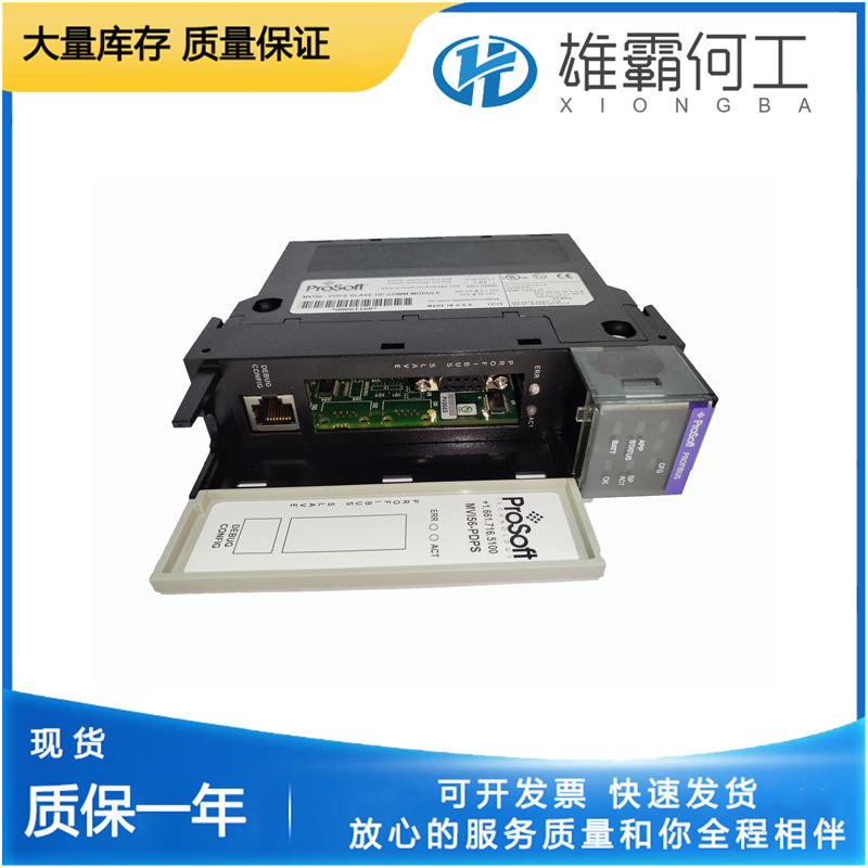
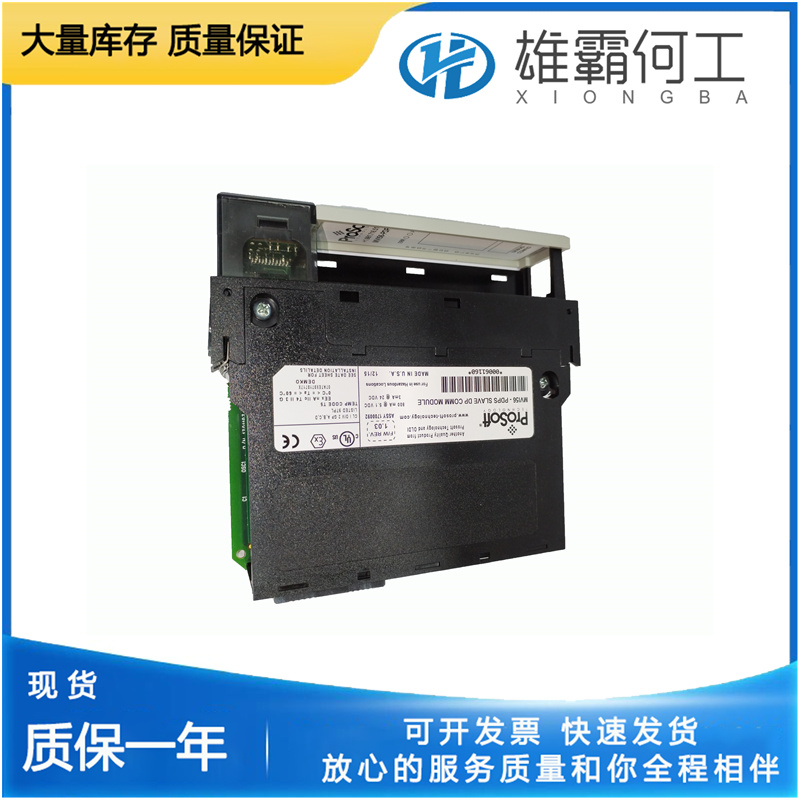
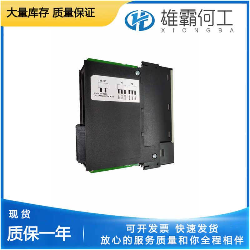
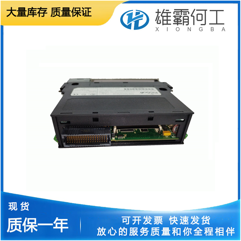
PROSOFT MVI56-PDPS CPU模块
有人建议,它与MVI56-PDPS控制器中标记的标签相似。寄存器/线圈要访问的状态RAM的所需区域。这四个区域是线圈(0x0000)、输入状态位(1x0000)、输入寄存器(3x0000)和保持寄存器(4x0000)。每个区域名称后面都是概念(直接)地址的最高有效数字,如括号所示。偏移要访问的数据在状态RAM内的所需偏移量。这与寄存器/线圈选择相结合,将确定要访问的数据的完整地址。例如,选择偏移量为00180的保持寄存器将产生400180的最终地址。数据类型访问数据所需的格式。寄存器/线圈类型的线圈和输入位只能作为byte_bools访问。可以通过以下方式之一访问寄存器:§ Int16-16位有符号整数§ MVI56-PDPS位有符号长整数§ Uint16-16位无符号整数§ MVI56-PDPS位无符号长整数§ Float32-32位浮点元素数要访问的元素数。这允许阵列传输。使用“西门子S7新标签”对话框将来自西门子S7控制器的标签添加到模块配置中。要打开“西门子S7新标记”对话框,请在“配置编辑器”树中选择西门子S7控制器下的“标记”节点,然后单击工具栏上的“新建”按钮。参数描述标记名称所需的标记名称,完全由用户决定。建议其与西门子S7控制器中标记的标签相似。地址类型要访问的内存类型:输入、输出、外围输入、标志位、定时器、计数器或数据块。输入包含输入模块最后一次扫描的存储器。该区域的S7符号(IEC)为“I”。此内存是只读的,用于模块访问。输出在下一个扫描周期结束时,包含要写入输出模块的所需输出值的存储器。
与标记关联的图元的名称、数据类型和数量显示在“新建标记”对话框的右侧。您不能修改任何标记值。单击ADD(添加)按钮,将Tag(标记)参考添加到模块的配置中。单击“完成”关闭“新建标记”对话框。当该对话框首次出现时,“标记”树中不会显示任何标记。对话框顶部是一个名为“标记过滤器”的编辑框。输入标记的过滤器,然后单击“获取标记”按钮或按[Enter]键。所有与指定筛选器匹配的标记都将加载到标记树中。或者,要获取所有标记,请将标记过滤器留空,然后单击“获取标记”按钮或按[ENTER]键。另请参阅标记过滤器(第72页)。将与过滤器匹配的标记加载到标记树中后,选择一个标记。MVI56-PDPS与标记关联的图元的名称、数据类型和数量显示在“新建标记”对话框的右侧。您不能修改任何标记值。单击ADD(添加)按钮,将Tag(标记)参考添加到模块的配置中。单击“完成”关闭“新建标记”对话框。当对话框首次出现时,位置树将加载控制器内的标记位置。对于PLC5、MicroLogix或SLC,这些都是文件参考。在位置树中选择标记位置。MVI56-PDPS标记关联的“文件地址”、“数据类型”和“名称”显示在“新建标记”对话框的右侧。您可以将标记的名称修改为对您有意义的标记名称。您可以修改元素的数量,以指定此位置将有多少数据项与此标记关联。当元素数大于1时,此标记将作为数组处理。单击添加按钮将标记添加到模块的配置中。单击完成关闭PLC5、MicroLogix和SLC新标签对话框使用Modbus TCP/IP新标签对话框将Schneider Electric Quantum PLC(Unity或Concept)控制器的标签添加到模块配置中。要打开Modbus TCP/IP新标签对话框,请在配置编辑器树中选择Schneider Electric Quantum PLC控制器下的标签节点,然后单击工具栏上的New按钮参数描述标签名称所需的标签名称,完全由用户决定。
They may contain the following data types: BOOL, BYTE, WORD, DWORD, INT, DINT, REAL, S5TIME, DATE, TIME, TIME_OF_DAY, CHAR, DATE_AND_TIME, STRING, or ARRAY. Descriptions of these data types should be available in the S7 PLC or Step 7 Programming Software documentation. This memory is read/write for module access. DB Number The number of the desired Data Block to access. This field is only valid if the Address Type selected is Data Blocks (DB). Offset The desired offset/number of the associated Address Type element. The following is a description of this field’s meaning for each address type: Input, Peripheral Input & Output Enter the slot number of the desired I/O module. Flag Bit Enter the byte offset within the Flag Bit memory of the desired location. Timers & Counters Enter the number of the desired timer or counter. Data Blocks Enter the number of the desired data block. Bit ID The desired bit number within the data element.MVI56-PDPS Data Type The desired format for accessing the data. This field depends on the selected Address Type.
The S7 notation (IEC) for this area is "PI". This area is read only for module access. Flag Bit The memory that is intended to store interim results calculated in the program of the PLC. The S7 notation (IEC) for this area is "M". This memory is read/write for module access.MVI56-PDPS Timers The memory that contains the accumulators for the timers in the S7 PLC. The S7 notation (IEC) for the timers is "T". This memory is read only for module access and the format is in BCD. The number represents the number of milliseconds that the timer has been active with a maximum value of 3999. Counters The memory that contains the accumulators for the counters in the S7. The S7 notation (IEC) for the counters is "C". This memory is read only for module access and the format is in BCD. The number represents the accumulated value of the counter since the counter has been active with a maximum value of 999.·Parameter Description Data Blocks The memory that contains information for the program of the S7 PLC.
Use the Siemens S7 New Tag dialog box to add Tags from a Siemens S7 controller to the module's configuration. To open the Siemens S7 New Tag dialog box, you select the Tags node under a Siemens S7 controller in the Configuration Editor tree and then click the NEW button on the toolbar.Parameter Description Tag Name The desired name of the tag and is completely at the discretion of the user.MVI56-PDPS It is suggested that it resemble the tag as it is labeled in the Siemens S7 controller. Address Type The type of memory to be accessed: Input, Output, Peripheral Input, Flag Bit, Timers, Counters, or Data Blocks. Input The memory that contains the last scan of the input modules. The S7 notation (IEC) for this area is "I". This memory is read-only for module access. Output The memory that contains the desired output values to be written to the output modules at the end of the next scan cycle. The S7 notation (IEC) for this area is "Q". This memory is read only for module access. Peripheral Input The actual physical hardware of the input modules.